- Publication year : 2023
1~20 item / All 20 items
Displayed results
Added to bookmarks
Bookmarks listBookmark has been removed
Bookmarks listYou can't add any more bookmarks
By registering as a member, you can increase the number of bookmarks you can save and organize them with labels.
Free membership registration
Contact this company
Contact Us Online1~20 item / All 20 items

Explaining the basic principles of high-frequency accelerators with diagrams! We also introduce the representative key performance of the LLRF radiation light equipment. The high-frequency technology and optical transmission technology that Tamagawa Electronics Co., Ltd. has cultivated over many years are applied to the high-frequency circuits of linear accelerators in large-scale radiation light facilities. Electron accelerators accelerate electrons and positrons to speeds close to the speed of light, achieving a high-energy state. When these electrons or positrons are bent by a magnetic field, the electromagnetic waves emitted in the direction of their travel are referred to as synchrotron radiation. In this column, we introduce the accelerator, high-frequency technology, and the representative key performance of the LLRF radiation light equipment. We encourage you to read it. [Contents] ■ Introduction ■ Accelerators and high-frequency technology ■ High-frequency precision unmatched by radios ■ Conclusion *For detailed content of the column, please refer to the related links. For more information, feel free to contact us.
Added to bookmarks
Bookmarks listBookmark has been removed
Bookmarks listYou can't add any more bookmarks
By registering as a member, you can increase the number of bookmarks you can save and organize them with labels.
Free membership registration
We provide proposals and designs from the product planning stage! We support better product development. (Applicable frequency ranges can be designed from HF band to millimeter wave band) This column introduces multifunctional modules (RF front ends). In beamforming technology used in 5G communications and active phased array technology used in various radar systems, multiple antenna elements are arranged to scan electronic beams through phase control, necessitating the need for multi-system integrated transmit and receive active modules. At Tamagawa Electronics, we leverage our long-established high-frequency technology and digital technology to develop multifunctional frequency conversion modules, providing products tailored to various needs. [Contents] ■ Introduction ■ Components that make up the RF front end ■ Support for multi-system integrated modules ■ Conclusion *For detailed content of the column, please refer to the related links. For more information, feel free to contact us.
Added to bookmarks
Bookmarks listBookmark has been removed
Bookmarks listYou can't add any more bookmarks
By registering as a member, you can increase the number of bookmarks you can save and organize them with labels.
Free membership registration
Introducing efforts towards high frequency and high-speed communication! An explanation of an example of a millimeter-wave device developed in the past. This column introduces the development of millimeter-wave and terahertz technology. In recent years, the acceleration and increase in capacity of communication have progressed. Meanwhile, the use of radio waves up to 275 GHz has been allocated by ITU-R and the Radio Law. However, due to the depletion of frequencies, research and development related to communication has been initiated in national projects and research institutions such as universities in Japan and Europe for the use of frequencies beyond this range. Please take a moment to read it. 【Contents】 ■ Introduction ■ Millimeter-wave technology ■ A brief introduction to our products ■ Conclusion *For detailed content of the column, please refer to the related links. For more information, feel free to contact us.
Added to bookmarks
Bookmarks listBookmark has been removed
Bookmarks listYou can't add any more bookmarks
By registering as a member, you can increase the number of bookmarks you can save and organize them with labels.
Free membership registration
Using a resin band on the steel frame allows for direct binding to the main body! An installation image is explained in the diagram! In this column, we introduce a DC-pass type attenuator for LPWA that can be installed outdoors and has a DC-pass circuit. The DC input current can handle up to 0.5A, and the DC input voltage can go up to 15Vdc. The frequency range supports from 700MHz to 2000MHz, making it versatile for various applications. Additionally, it complies with waterproof grade IPX65, so it won't break even when directly exposed to water jets from various directions. Please take a moment to read it. 【Contents】 ■ Product Overview ■ Applications ■ Electrical Characteristics Data ■ Installation Image *For detailed content of the column, please refer to the related links. For more information, feel free to contact us.
Added to bookmarks
Bookmarks listBookmark has been removed
Bookmarks listYou can't add any more bookmarks
By registering as a member, you can increase the number of bookmarks you can save and organize them with labels.
Free membership registration
Explaining the "Advantages of Analog Optical Transmission" and the "Counter Performance of 10MHz to 3GHz E/O and O/E Converters"! Tamagawa Electronics has developed analog optical transmission devices since the second generation mobile PDC era as a countermeasure against insensitivity, responding to customer needs. In this column, we introduce the analog RoF technology that has been cultivated in our company over many years. RoF stands for Radio over Fiber, which refers to optical fiber wireless. The E/O converter converts [electricity to light], the transmission is done via optical fiber, and the O/E converter converts [light to electricity] to demodulate the electrical signal. Please take a moment to read it. 【Contents】 ■ Introduction ■ Advantages of Analog Optical Transmission ■ High-Reliability Optical Transmission Devices ■ EOC-144/OEC-1041 Counter Performance ■ Future Plans *For detailed content of the column, please refer to the related links. For more information, feel free to contact us.
Added to bookmarks
Bookmarks listBookmark has been removed
Bookmarks listYou can't add any more bookmarks
By registering as a member, you can increase the number of bookmarks you can save and organize them with labels.
Free membership registration
Introducing a simple example of developing a digital PLL circuit using freely available software that anyone can easily access! Our company prides itself on being one of the leading experts in microwave technology in Japan, but in recent years, we have also begun to focus on digital technology in line with the times. In this column, we present a simple example of our efforts in "software-based digital circuit development (high-level synthesis)" aimed at improving productivity and maintainability in the development of digital devices, as well as addressing labor shortages. We invite you to read on. [Contents (partial)] ■ Introduction ■ Simple Digital PLL ■ Software Development Environment and Implementation Targets ■ Specifications and System Diagram ■ Simple Loop Design *For detailed content of the column, please refer to the related links. For more information, feel free to contact us.
Added to bookmarks
Bookmarks listBookmark has been removed
Bookmarks listYou can't add any more bookmarks
By registering as a member, you can increase the number of bookmarks you can save and organize them with labels.
Free membership registration
The chip integration has made it possible to easily create high-performance wideband synthesizers without the need for complex circuits! In this column, we introduce single-chip wideband synthesizers. Starting with the "VCO-integrated microwave wideband synthesizer simple block," we explain various applications of wideband synthesizers, such as "simple spectrum analyzers" and "direct conversion circuits," with diagrams. Recently, wideband synthesizers that cover up to the submillimeter wave band have been released by semiconductor manufacturers, allowing for smaller board mounting areas and simpler implementations. We invite you to read on. [Contents] ■ Application examples ■ Phase noise *For detailed content of the column, please refer to the related links. For more information, feel free to contact us.
Added to bookmarks
Bookmarks listBookmark has been removed
Bookmarks listYou can't add any more bookmarks
By registering as a member, you can increase the number of bookmarks you can save and organize them with labels.
Free membership registration
Tunable filters can be broadly classified into variable bandwidth fixed type and absolute bandwidth fixed type! Introducing the newly developed variable filter and its technology. This column introduces tunable filters. As the name suggests, a tunable filter is a filter that can change its frequency characteristics. In communication systems, for example, when the frequency band of the radio waves used is wide and cannot be accommodated by a conventional frequency-fixed filter, tunable filters become necessary. Our company has developed and commercialized numerous tunable filters. This time, we will introduce the newly developed filter and its technology. Please take a moment to read. 【Contents】 ■ Introduction ■ Design of Tunable Filters ■ Developed Tunable Filters *For detailed content of the column, please refer to the related links. For more information, feel free to contact us.
Added to bookmarks
Bookmarks listBookmark has been removed
Bookmarks listYou can't add any more bookmarks
By registering as a member, you can increase the number of bookmarks you can save and organize them with labels.
Free membership registration
By incorporating SDR into the system, we standardize the hardware and enable various methods through software! Information on the structure of SDR and more is included. This column introduces the SDR that we are also developing. SDR stands for Software Defined Radio, which translates to software radio. In simple terms, it is a radio device that can change its functions through software. We provide detailed explanations on topics such as "What is SDR?", "What is the structure of SDR?", and "What kinds of SDR are available?" Please take a moment to read it. [Contents] ■ Introduction ■ What is SDR? ■ What is the structure of SDR? ■ What kinds of SDR are available? ■ A brief product introduction *For more detailed content of the column, please refer to the related links. For further inquiries, feel free to contact us.
Added to bookmarks
Bookmarks listBookmark has been removed
Bookmarks listYou can't add any more bookmarks
By registering as a member, you can increase the number of bookmarks you can save and organize them with labels.
Free membership registration
Introducing the operating principle of supplying power over several kilometers using lightweight, bend-resistant, and easy-to-handle optical fibers, illustrated with diagrams! This column presents optical fiber power supply technology and its applications. We explain the operating principles of optical fiber power supply, examples of system configurations, the principles of optical conversion, and examples of sensor heads using diagrams and photographs. Utilizing the low loss of optical fibers (0.3 dB/km), we introduce technology that transmits energy through optical fibers and supplies power over several kilometers, even in locations without a power source. [Contents] ■ Introduction ■ Examples of applications for optical fiber power supply *For detailed content of the column, please refer to the related links. For more information, feel free to contact us.
Added to bookmarks
Bookmarks listBookmark has been removed
Bookmarks listYou can't add any more bookmarks
By registering as a member, you can increase the number of bookmarks you can save and organize them with labels.
Free membership registration
The receiver and controller are connected via optical fiber! Low disturbance and continuous measurement are possible! We would like to introduce a case where "Optical Power Supply ROF (Receiver)" was implemented in EMC testing equipment. The receiver, which detects RF signals using optical energy for power supply, is electrically insulated, allowing for low disturbance and continuous measurement. Since optical fiber has extremely low transmission loss, high-frequency (RF) signals can be transmitted without loss and are not affected by radio waves. Additionally, optical fiber is made of insulating material, and it converts and transmits signals from the current probe into light, eliminating any inductive effects. 【Case Overview】 ■ Installation Site: FA (EMC Testing Equipment) ■ Installed Product: Optical Power Supply ROF (Receiver) *For more details, please refer to the related links or feel free to contact us.
Added to bookmarks
Bookmarks listBookmark has been removed
Bookmarks listYou can't add any more bookmarks
By registering as a member, you can increase the number of bookmarks you can save and organize them with labels.
Free membership registration
We provide optical conversion units, amplifiers, and attenuators for use in optical relay systems, as well as coaxial filters and combiners for onboard radio equipment! We would like to introduce a case study of the implementation of "SCM for train radio, optical transmission, and combiners for onboard radio equipment" in transportation radio facilities. In wireless equipment that communicates between trains and operation command centers, there is an LCX (leaky coaxial cable) communication method as a means of communication with moving trains. The optical relay system converts and transmits radio signals into optical signals, relaying between the optical master station and optical slave stations. Our company provides optical conversion units, amplifiers, and attenuators for use in optical relay systems, as well as coaxial filters and combiners for onboard radio equipment. [Case Overview] ■ Implementation Location: Public Social Infrastructure (Transportation Radio Facilities) ■ Implemented Products: SCM for Train Radio, Optical Transmission, Combiners for Onboard Radio Equipment *For more details, please refer to the related links or feel free to contact us.
Added to bookmarks
Bookmarks listBookmark has been removed
Bookmarks listYou can't add any more bookmarks
By registering as a member, you can increase the number of bookmarks you can save and organize them with labels.
Free membership registration
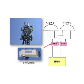
Compliant with IP67! It is used for the purpose of separating the necessary frequencies for a shared antenna. We would like to introduce a case where a "frequency combiner (for mobile phone base stations)" was implemented in base station equipment. This product is used when sharing multiple frequency radio signals or when separating shared signals, with the aim of reducing the number of power supply lines from each base station and separating the necessary frequencies for the shared antenna. In the case of an infrastructure sharing system, it can be used when sharing and separating the radio signals of each mobile phone operator. [Case Overview] ■ Implementation Location: Mobile Phone Related (Base Station Equipment) ■ Implemented Product: Frequency Combiner (for Mobile Phone Base Stations) *For more details, please refer to the related links or feel free to contact us.
Added to bookmarks
Bookmarks listBookmark has been removed
Bookmarks listYou can't add any more bookmarks
By registering as a member, you can increase the number of bookmarks you can save and organize them with labels.
Free membership registration
A configuration that minimizes the amplitude and phase difference of each system to the limit! A case study of equipment for aircraft-mounted radar detection devices. We would like to introduce a case where the "aircraft-mounted radio reception front end" was implemented in equipment for government agencies. This product is equipment for aircraft-mounted radar detection devices, designed to enable wideband reception by minimizing the amplitude and phase difference of each system to the limit. It also meets the requirements for aircraft-mounted equipment to withstand harsh environments (MIL standards compliant). 【Case Overview】 ■ Implementation Location: Government Agencies (Mounted Equipment) ■ Implemented Product: Aircraft-mounted Radio Reception Front End *For more details, please refer to the related links or feel free to contact us.
Added to bookmarks
Bookmarks listBookmark has been removed
Bookmarks listYou can't add any more bookmarks
By registering as a member, you can increase the number of bookmarks you can save and organize them with labels.
Free membership registration
Achieving fixtures that are difficult to oscillate! Full automation is possible from test condition setting, current testing, to data acquisition. Our company has a long history of delivering high-frequency power FET current testing equipment to major semiconductor manufacturers in Japan. We provide custom solutions tailored to various functions based on customer applications, such as reliability testing for newly developed devices and use in production lines. Additionally, we leverage our expertise as a manufacturer of high-frequency components to design fixtures that accommodate increasingly smaller and more complex device packages, offering customized designs that consider high-frequency characteristics and long-term maintenance according to customer requests. 【Case Overview】 ■ Installation Site: FA (Semiconductor Testing Equipment) ■ Installed Product: Semiconductor Burn-In Equipment (RF/DC) *For more details, please refer to the related links or feel free to contact us.
Added to bookmarks
Bookmarks listBookmark has been removed
Bookmarks listYou can't add any more bookmarks
By registering as a member, you can increase the number of bookmarks you can save and organize them with labels.
Free membership registration
It is possible to manufacture at a low cost by using commercial off-the-shelf components! A case study of a radar transceiver installed on a satellite. We would like to introduce a case where a "satellite-mounted transceiver" was implemented on a satellite. By extensively using commercial components, this product significantly reduces costs compared to conventional products, making it possible to manufacture at a low price. Although commercial components are used, we conduct environmental tests such as thermal vacuum tests, vibration tests, and shock tests to confirm normal operation in the space environment. [Case Overview] ■ Implementation Destination: Space and Satellite Related (Artificial Satellite) ■ Implemented Product: Satellite-mounted Transceiver *For more details, please refer to the related links or feel free to contact us.
Added to bookmarks
Bookmarks listBookmark has been removed
Bookmarks listYou can't add any more bookmarks
By registering as a member, you can increase the number of bookmarks you can save and organize them with labels.
Free membership registration
The radio waves are transmitted via optical fiber to areas where the signal is weak, such as indoors or dead zones, connecting to multiple antennas through several photon devices for wireless communication. We would like to introduce a case where the "Airport DAS System" was implemented in transportation radio equipment. The Optical DAS System (Optical Fiber DAS, Distributed Antenna System, Optical Repeater) is a light transmission system designed to address dead zones, aimed at increasing the number of lines and functionality. It has scalability at the unit level, making it easy to expand the wireless area. By operating in conjunction with monitoring applications using Ethernet, it allows for the monitoring of devices in operation, and in the event of an anomaly, it also has a notification function that sends alerts to registered users via email. 【Case Overview】 ■ Installation Location: Public Social Infrastructure (Major Airports in the Country) ■ Installed Product: Airport DAS System *For more details, please refer to the related links or feel free to contact us.
Added to bookmarks
Bookmarks listBookmark has been removed
Bookmarks listYou can't add any more bookmarks
By registering as a member, you can increase the number of bookmarks you can save and organize them with labels.
Free membership registration
5G base station output level adjustment attenuators, couplers, splitters, etc.! We will introduce examples of their implementation in mobile phone base station equipment! In mobile phone base stations, various methods are used to establish the necessary communication areas depending on the installation location. For outdoor area base stations, small low-power units and large high-power base stations are used interchangeably according to the coverage range of the communication area in urban, suburban, and mountainous regions. In indoor area base stations, to cover areas where radio waves are difficult to reach, such as each floor of high-rise buildings, subways, and underground shopping streets, communication areas are established using indoor antenna sharing systems and other methods. At Tamagawa Electronics, we provide components for 5G base stations, including coaxial attenuators for adjusting mobile phone signal levels and couplers and splitters for branching antennas, available in both outdoor and indoor types according to the installation area. *For more details, please refer to the related links or feel free to contact us. Special site Related link - https://www.tmele.jp/case/297/
Added to bookmarks
Bookmarks listBookmark has been removed
Bookmarks listYou can't add any more bookmarks
By registering as a member, you can increase the number of bookmarks you can save and organize them with labels.
Free membership registration
Light conversion section ~ AD/DA conversion section ~ Frequency conversion section ~ Antenna module can be designed in a one-stop manner! Introducing case studies for government agencies (radar)! We present a case study of the "Front-end Module for Active Phased Array Radar" implemented in government agency radars. Radar sites installed in various locations in Japan monitor and guard the area and surrounding airspace. In recent years, active phased array radar has become mainstream, aiming to improve responsiveness to low RCS targets such as flying objects. Tamagawa Electronics has a proven track record in implementing front-end modules that up/down convert frequencies in the RF band directly below the antenna and in the baseband IF band. 【Case Overview】 ■ Implementation Location: Government Agency (Radar) ■ Implemented Product: Front-end Module for Active Phased Array Radar *For more details, please refer to the related links or feel free to contact us.
Added to bookmarks
Bookmarks listBookmark has been removed
Bookmarks listYou can't add any more bookmarks
By registering as a member, you can increase the number of bookmarks you can save and organize them with labels.
Free membership registration
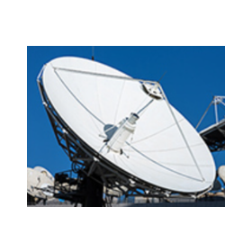
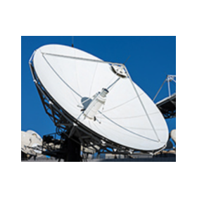
Compatible with 19-inch standard racks! Examples of products that are resistant to external noise due to fiber optic transmission. We would like to introduce a case where a "fiber optic link for satellite ground stations" was implemented in satellite ground station equipment. Radio waves from space, such as satellite broadcasting (BS, CS), are received by remote antennas on the ground. The received signal is downconverted (frequency converted) and transmitted as an IF signal from the antenna to the station (receiver). The distance between the antenna and the station is several hundred meters to several kilometers, and using coaxial cables results in significant loss, so we use a fiber optic transmission device called "RoF." 【Case Overview】 ■ Installation Site: Space and Satellite Related (Satellite Ground Station Equipment) ■ Installed Product: Fiber Optic Link for Satellite Ground Stations *For more details, please refer to the related links or feel free to contact us.
Added to bookmarks
Bookmarks listBookmark has been removed
Bookmarks listYou can't add any more bookmarks
By registering as a member, you can increase the number of bookmarks you can save and organize them with labels.
Free membership registration