We have compiled a list of manufacturers, distributors, product information, reference prices, and rankings for CAD.
ipros is IPROS GMS ・ IPROS One of the largest technical database sites in Japan that collects information on.

CAD(メカ) - List of Manufacturers, Suppliers, Companies and Products | IPROS GMS

Last Updated: Aggregation Period:Sep 09, 2026~Oct 06, 2026
This ranking is based on the number of page views on our site.

CAD Product List

1~9 item / All 9 items

Displayed results

Proposal for Utilizing CAD: Reasons to Choose BricsCAD

3D-BIM, providing mechanical functions on a single platform! Introducing the secrets of high compatibility and reliability.

This article introduces why "BricsCAD" is chosen in many design environments. Under the concept of "One platform, One file format," it offers 2D, 3D, and BIM, as well as mechanical functions all on a single platform. Everything can be created in the industry-standard .dwg file format. The related links below provide a detailed explanation of why it has garnered significant attention and is highly regarded in design environments across a wide range of industries, including manufacturing, architecture, and civil engineering. Please take a moment to read it. [Contents] ■ About Bricsys ■ History of BricsCAD / Compatible CAD ■ Value of BricsCAD *You can view the detailed content of the article through the related links. For more information, please feel free to contact us.

Added to bookmarks

Bookmarks list

Bookmark has been removed

Bookmarks list

You can't add any more bookmarks

By registering as a member, you can increase the number of bookmarks you can save and organize them with labels.

Free membership registration

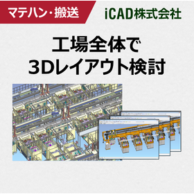
Presentation of case studies. What is the 3D CAD required for the design of material handling and transportation equipment?

3D CAD that achieves a reduction in lead time for transportation equipment development! Realizing ultra-fast response capable of handling 3 million parts in 0.2 seconds.

In the design of conveying equipment, the requirements vary for each customer due to factors such as the conveyed items and factory layout, necessitating a unique and quick turnaround design for each case. To achieve a vertical startup of the equipment, it is crucial to extract detailed customer requirements at an early stage of specification discussions and to help them quickly understand the structure and operability of the equipment. For mechanical designers, the 3D CAD iCAD SX achieves high-speed response, handling 3 million parts in 0.2 seconds. You can manage the entire conveying equipment, including material handling devices like conveyors and AGVs, on 3D CAD without stress. Since the movements of the machinery can be simulated in advance for the entire system, there is no worry about damaging the machinery or causing harm to people. This leads to improved design quality and reduced development lead times. \\Customer case studies that have realized manufacturing DX are exclusively available on the 【special site】/ /                     ^^^^^^^^^^^^^ ▶ Click on the special site to download the case studies now!  ↓↓↓

Added to bookmarks

Bookmarks list

Bookmark has been removed

Bookmarks list

You can't add any more bookmarks

By registering as a member, you can increase the number of bookmarks you can save and organize them with labels.

Free membership registration

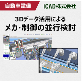
Realizing parallel examination of mechanics and control! 3D CAD suitable for automotive equipment design.

Achieving front-loading in automotive equipment development, including control and robot verification! Ultra-fast response 3D CAD that smoothly handles large-scale data.

In the automotive industry, there is a demand for the rapid market introduction of new vehicles, which requires the development of automotive production equipment with short delivery times and high quality. Additionally, not only mechanical design but also PLC simulation of equipment and welding robot simulation are becoming more complex, leading to the use of simulators for pre-validation. However, general simulation software requires the conversion of 3D CAD data, necessitating the reconfiguration of mechanisms and IO information with each design change. This makes it difficult to conduct parallel considerations in line with design progress, and many customers may have given up on this approach. To solve this issue, it is important to achieve control debugging and robot simulation directly on the 3D CAD platform. iCAD SX offers ultra-fast response by processing 3 million parts in 0.2 seconds, allowing it to handle vast amounts of data, including the operation and control information of large-scale models, and enables control debugging and robot simulation directly on the 3D CAD. This facilitates an earlier start to control design, shortening the equipment development period and achieving front-loading. ▶ A special site is currently showcasing limited case studies!    ↓↓↓

Added to bookmarks

Bookmarks list

Bookmark has been removed

Bookmarks list

You can't add any more bookmarks

By registering as a member, you can increase the number of bookmarks you can save and organize them with labels.

Free membership registration

Piping and wiring design

Large-scale routing on 3D CAD assemblies! Significant reduction in rework labor at the manufacturing site through prior wiring considerations.

In mechanical devices and production/plant equipment, it is important to be able to consider not only the mechanics but also the piping, wiring, and steel materials while confirming the surrounding arrangements. However, the following issues arise at the design site. 【Common Concerns】 - The 3D CAD data is heavy, making it difficult to consider piping and wiring. - Since piping and wiring are designed using specialized software, any modifications on the mechanical side require restarting the 3D CAD each time. - Using multiple software makes it difficult to maintain consistency. - Design reviews are conducted with a viewer, so modifications cannot be made on the spot. All of the above issues can be resolved. With COLMINA Design and Manufacturing Support iCAD SX (hereinafter referred to as iCAD), we have achieved a processing performance of 0.2 seconds for 3 million parts through the incorporation of proprietary technology. We have succeeded in reducing the weight of 3D data to about 1/50 of its original weight (compared to our company), and by accumulating and utilizing all information on large-scale piping, wiring, and steel materials in iCAD, we support the realization of manufacturing DX. For details, please download the catalog and check it.

Added to bookmarks

Bookmarks list

Bookmark has been removed

Bookmarks list

You can't add any more bookmarks

By registering as a member, you can increase the number of bookmarks you can save and organize them with labels.

Free membership registration

What is the 3D CAD required for semiconductor manufacturing equipment design?

3D CAD that achieves a reduction in lead time for semiconductor equipment development! Realizing ultra-fast response handling of 3 million parts in 0.2 seconds.

In recent years, the development of semiconductor manufacturing equipment has seen a tremendous increase in the number of components due to the complexity of the required functions. Therefore, the biggest challenge is how to efficiently arrange various mechanical devices within a limited space. 'iCAD SX V8' is a domestically developed 3D CAD specialized for mechanical design, created to support Japanese manufacturing. iCAD achieves high-speed response, handling 3 million components in 0.2 seconds, allowing for stress-free design consideration and verification of the entire semiconductor manufacturing equipment, which can involve tens of thousands of parts. Leveraging its ability to handle vast amounts of information, it is possible to accumulate and utilize design information necessary for equipment development, including piping, wiring, and control (movement), all within a single CAD data file. This data can be used across various scenarios and departments, from design to manufacturing, assembly, and maintenance. *Case studies from semiconductor manufacturing equipment manufacturers are currently available for limited viewing on a special website. Please click the link below to download.

Added to bookmarks

Bookmarks list

Bookmark has been removed

Bookmarks list

You can't add any more bookmarks

By registering as a member, you can increase the number of bookmarks you can save and organize them with labels.

Free membership registration

[BIM Software Implementation Case Study] Mechanical (Cultural Center)

Adopting an appropriate solution! A case where work was coordinated through open communication.

This project connects two reinforced concrete structures using steel trusses with concrete slabs on each floor. The complexity of the joints in the steel structure, as well as the joints between the steel and reinforced concrete structures, increased due to their shapes and angles, becoming a challenge for the project. By maintaining open communication among the design architects, structural engineers, and fabrication team, we were able to smoothly discuss and adopt appropriate solutions even for very challenging aspects of the overall steel construction. 【Case Overview】 ■Challenges - Complexity of the joints in the steel structure - Increased complexity of the joints between the steel and reinforced concrete structures due to their shapes and angles ■Result: We were able to adopt appropriate solutions *For more details, please refer to the PDF materials or feel free to contact us. (If the PDF button is not displayed) ⇩The catalog can be downloaded from the special website below⇩

  • Software (middle, driver, security, etc.)
  • Other CAD related software
  • CAD

Added to bookmarks

Bookmarks list

Bookmark has been removed

Bookmarks list

You can't add any more bookmarks

By registering as a member, you can increase the number of bookmarks you can save and organize them with labels.

Free membership registration

Integrated Electronic CAD System

An integrated electronic CAD system ideal for the design and development of printed circuit boards and circuits.

It can be operated as an integrated electronic CAD system. We have realized high functionality to simplify operations from circuit diagram creation to printed circuit board design, making it widely usable for both beginners and professional designers. Additionally, by achieving collaborative design from PCB to 3D, we will shorten product lead times. 【Features】 -40% Project From circuit diagram design to printed circuit board design/3D, seamless and easy integration can reduce the designer's workload, enabling a reduction in design time【-40% Project】. With capabilities in graphic processing that consider not only single-sided designs but also high multilayer boards and flexible boards, designers can create their intentions without stress. Furthermore, through integration with various simulation functions, we promise a high-quality design environment.

  • Other CAD
  • CAD

Added to bookmarks

Bookmarks list

Bookmark has been removed

Bookmarks list

You can't add any more bookmarks

By registering as a member, you can increase the number of bookmarks you can save and organize them with labels.

Free membership registration

[Free trial available] Manufacturing design CAD "ARES Mechanical"

"ARES Mechanical," a CAD designed for manufacturing that caters to the needs of 2D mechanical CAD users and 3D CAD users.

ARES Mechanical" is a DWG-compatible CAD designed for mechanical designers and manufacturers. It provides appropriate tools for "Factory Layout Planners" who consider efficiency in machine installation planning and "Maintenance Engineers" who modify existing DWG drawings. Additionally, "Concept Designers" can quickly create sketches and technical drawings. It allows for the creation of standard drawings with complete DWG compatibility. It supports not only domestic design standards like JIS but also international standards such as ISO and German standards like DIN, along with various countries' scale standards. It includes a tool library for screws, bolts, and essential functions for mechanical design such as BOM and Balloons, which are indispensable for mechanical drawings. ▼ Free Trial Version Available We offer a trial version that allows you to use the latest version for free for 30 days. Please try out the high compatibility and excellent operability of "ARES Mechanical.

  • 2D CAD Construction
  • 2D CAD machine
  • 3D CAD
  • CAD

Added to bookmarks

Bookmarks list

Bookmark has been removed

Bookmarks list

You can't add any more bookmarks

By registering as a member, you can increase the number of bookmarks you can save and organize them with labels.

Free membership registration