We have compiled a list of manufacturers, distributors, product information, reference prices, and rankings for soft.
ipros is IPROS GMS ・ IPROS One of the largest technical database sites in Japan that collects information on.

soft(3D CAD) - List of Manufacturers, Suppliers, Companies and Products | IPROS GMS

Last Updated: Aggregation Period:Sep 16, 2026~Oct 13, 2026
This ranking is based on the number of page views on our site.

soft Product List

541~570 item / All 744 items

Displayed results

Comprehensive PCB Design Check Software! PCB Design Check

This is a verification-specific software that allows you to easily check and validate data related to circuit board design, such as spacing between patterns, without the need for specialized CAD software.

The comprehensive check software for printed circuit boards, PCB Design Check, is a verification-specific software that allows you to easily verify the data of circuit board designs, including checks and spacing between patterns, without the need for specialized CAD software. User registration is free and includes support, with no maintenance fees whatsoever!! By adding NC data to Gerber data and incorporating mounting data, it becomes possible to perform CAD design verification from manufacturing data of various CAD systems. It supports standard Gerber formats and also extends to the extended Gerber format (RS-274X), but does not support custom apertures or some specific functions.

  • Other CAD related software
  • 2D CAD Electrical
  • 2D CAD machine
  • soft

Added to bookmarks

Bookmarks list

Bookmark has been removed

Bookmarks list

You can't add any more bookmarks

By registering as a member, you can increase the number of bookmarks you can save and organize them with labels.

Free membership registration

Instantly solve geometric tolerance questions! The era when 3D CAD tools become educators.

No need to worry if you don't have knowledge of specifications! We support practical GD&T education.

The Creo GD&T Advisor Extension is not just a tool for checking tolerances; it is also a powerful educational platform with rich help content built in. Even designers who are unfamiliar with GD&T standards can acquire knowledge while progressing with their work. If questions or errors arise regarding the application of GD&T during design, help can be accessed with a simple right-click on the messages displayed in the Advisor Tree. This help feature provides detailed information on the principles of GD&T, interpretations of the standards, and specific solutions to errors. As a result, designers can refer to the standards and acquire GD&T knowledge in a practical context without interrupting their work. This feature eliminates the hassle of flipping through standard documents and allows for immediate access to correct information, significantly contributing to the improvement of GD&T skill levels across the entire design team. Examples of tutorials are also included. For more details on the helpful features that aid in knowledge acquisition, please refer to the documentation. *For more information, please download the PDF or feel free to contact us.*

  • 3D CAD
  • soft

Added to bookmarks

Bookmarks list

Bookmark has been removed

Bookmarks list

You can't add any more bookmarks

By registering as a member, you can increase the number of bookmarks you can save and organize them with labels.

Free membership registration

Area Calculation Tool for ARCHICAD

Perform area calculations and create area diagrams with simple operations.

The Quantity Calculation Tool for ARCHICAD is an add-on system (Windows only) that streamlines the quantity calculation tasks, which have played a significant role in the design process. It allows for efficient area calculations from pre-entered 3D building models and 2D drawings with simple operations. The tool supports various tasks, from starting the creation of quantity calculation drawings to making revisions in response to plan changes, enabling accurate and speedy area calculations and drawing creation.

  • Other CAD related software
  • soft

Added to bookmarks

Bookmarks list

Bookmark has been removed

Bookmarks list

You can't add any more bookmarks

By registering as a member, you can increase the number of bookmarks you can save and organize them with labels.

Free membership registration

[Case Study of 3D CAD Software for Mechanical Design] Toshiba Electronic Engineering Co., Ltd.

[Free Case Study] Conceptual design of electronic component manufacturing equipment accelerated with the use of 3D CAD!

We would like to introduce a case study of the implementation of "iCAD SX" at Toshiba Electronic Engineering Corporation's Equipment Technology Center. The company has chosen to apply high-end CAD to electronic components and mold design, and to perform 3D design only in situations where 3D modeling is effective in equipment design, while continuing to use 2D design where 2D data suffices. After the implementation, they were able to significantly speed up the conceptual design process of manufacturing equipment, drafting work after detailed design, and the creation of technical documents such as operation manuals, which often require design changes. [Case Overview] ■ Reasons for Adoption - Ability to apply 3D in conceptual design - Smooth handover of drawings to external partner companies responsible for manufacturing ■ Results - Easy-to-understand 3D images enhance communication with overseas manufacturers *For more details, please refer to the PDF document or feel free to contact us.

Added to bookmarks

Bookmarks list

Bookmark has been removed

Bookmarks list

You can't add any more bookmarks

By registering as a member, you can increase the number of bookmarks you can save and organize them with labels.

Free membership registration

[Case Study of 3D CAD Software for Mechanical Design] Kobayashi Manufacturing Co., Ltd.

[Free Case Study Provided] Achieve a significant improvement in design efficiency and acquire a highly scalable design development environment!

We would like to introduce a case study of the implementation of "iCAD SX" at Kobayashi Seisakusho Co., Ltd., a manufacturer of paper-making machinery. The product was introduced with the aim of shortening lead times through information sharing among designers and integration with the material purchasing system. We successfully established a development environment that enables smooth data exchange with external parties and can flexibly respond to functional expansions such as material purchasing integration. 【Case Overview】 ■Challenges - Need for a CAD system to support the engineering company ■Results - Achieved smooth data exchange with external parties - Successfully established a development environment that can flexibly respond to functional expansions such as material purchasing integration *For more details, please refer to the PDF materials or feel free to contact us.

Added to bookmarks

Bookmarks list

Bookmark has been removed

Bookmarks list

You can't add any more bookmarks

By registering as a member, you can increase the number of bookmarks you can save and organize them with labels.

Free membership registration

Solid Edge Basic Experience Seminar

[Free Participation] It's okay if you're new to 3D CAD! A 3D CAD that allows you to design quickly and as you envision.

This is a seminar for those interested in Solid Edge, where even beginners in 3D CAD can experience Solid Edge's synchronous technology. It is held regularly in Tokyo, Nagoya, and Osaka. We hope you can join us! 【Solid Edge Basic Experience Seminar Content】 ● Introduction to Solid Edge ● Basic Operations ● Model Creation (Synchronous Technology) ● Assembly Creation ● Drawing Creation *For more details, please download the catalog or contact us.

  • Company:TAC
  • Price:Other
  • 3D CAD
  • soft

Added to bookmarks

Bookmarks list

Bookmark has been removed

Bookmarks list

You can't add any more bookmarks

By registering as a member, you can increase the number of bookmarks you can save and organize them with labels.

Free membership registration

Explanatory Material "SOLIDWORKS SWIFT Technology"

The "ease of use" of SOLIDWORKS was a secret of this SOLIDWORKS SWIFT technology!

White Paper Available Now!! Many designers understand the wonderful features of 3D CAD, but feel that it takes a lot of time to master CAD operations in order to recognize the true benefits. SOLIDWORKS' SWIFT technology is one of the technologies that allows users to recognize the advantages of three-dimensional CAD without having to master complex techniques. We are currently offering a free "White Paper" that thoroughly analyzes and explains SWIFT technology! ▼ The white paper can be downloaded from the link below ▼

  • 3D CAD
  • Other CAD
  • Other CAD related software
  • soft

Added to bookmarks

Bookmarks list

Bookmark has been removed

Bookmarks list

You can't add any more bookmarks

By registering as a member, you can increase the number of bookmarks you can save and organize them with labels.

Free membership registration

LinkCAD

It features an intuitive user interface that guides you through each step of the conversion process!

"LinkCAD" is software that converts mask and PCB layouts between many formats such as DXF, Gerber RS-274X, GDSII, CIF, PDF, PostScript, SVG, and PNG. It is possible to import raster image files and convert them into vector formats. Additionally, using layer operations, you can perform calculations such as addition, subtraction, intersection, and union between layers. 【Features (partial)】 ■ View - It is possible to display the layouts before and after conversion in 2D or 3D. - Operations such as zooming, panning, and rotating are possible. ■ Transform - You can change the size and position of the layout, as well as rotate, flip, or mirror it. *For more details, please refer to the related links or feel free to contact us.

  • Company:B7
  • Price:Other
  • Data conversion software
  • soft

Added to bookmarks

Bookmarks list

Bookmark has been removed

Bookmarks list

You can't add any more bookmarks

By registering as a member, you can increase the number of bookmarks you can save and organize them with labels.

Free membership registration

[Case Study of 3D CAD Software for Mechanical Design] Harmony Co., Ltd.

Free provision of case studies: Implemented in the design of industrial robots to meet the needs for weight reduction and space saving!

We would like to introduce a case study of the implementation of "ICAD SX/Mechanical PRO" at Harmon Co., Ltd., a manufacturer of robots for extracting molded products from plastic injection molding machines and surrounding rationalization equipment. The impetus for the implementation was the request to shorten the time required to create parts lists. Previously, creating this 3D diagram took a significant amount of time. By utilizing this product for complete 3D CAD design, we promoted the "visualization" of design, enabling the sharing of designers' intentions and knowledge, which transformed the process into one that produces high-performance products from the very beginning of the design phase. 【Case Overview】 ■Challenges - It took a considerable amount of time to create parts lists. - There were instances where parts lists could not be completed in time for the launch of new products. ■Results - The number of prototypes for standard products and the time required for prototyping were reduced to less than half. - By utilizing analysis, design quality improved, and optimal designs became possible. *For more details, please refer to the PDF document or feel free to contact us.

Added to bookmarks

Bookmarks list

Bookmark has been removed

Bookmarks list

You can't add any more bookmarks

By registering as a member, you can increase the number of bookmarks you can save and organize them with labels.

Free membership registration

Shibaura Mechatronics Co., Ltd. [3D CAD Implementation Case] i CAD SX

A 3D CAD that smoothly carries out the assembly design of 40,000 parts, achieving "zero interference" and "reduction of rework in the manufacturing process."

We would like to introduce a case study of business improvement using the 3D CAD "iCAD SX," which is specialized in mechanical design. "Shibaura Mechatronics Corporation" decided to transition to 3D design in order to improve the efficiency of their semiconductor manufacturing equipment design operations. After comparing three products: an existing 2D CAD from the same manufacturer, a high-end 3D CAD, and iCAD SX, they selected "iCAD SX" as the only one that could withstand practical use. As a result, despite being custom-made products without a prototyping process, they achieved "zero interference" at the design stage. By utilizing 3D data and a viewer, they successfully reduced the man-hours required for creating assembly instruction manuals. [Main Benefits of Implementation] - Achieved "zero interference" at the design stage, reducing rework costs in the manufacturing process. - Reduced design time by 30% compared to the time estimated with 2D CAD. - Increased inquiries through visual appeal. [Download Materials] - Currently available for limited access on the special site. Please click the link below.    ▼▼▼ Click here ▼▼▼

Added to bookmarks

Bookmarks list

Bookmark has been removed

Bookmarks list

You can't add any more bookmarks

By registering as a member, you can increase the number of bookmarks you can save and organize them with labels.

Free membership registration

Robot programming support software "neoROSET"

neoROSET is a programming tool that allows for robot programming and accurate simulation on a PC.

neoROSET is a programming tool that allows for robot programming and accurate simulation on a PC. By conducting offline verification in advance, it mitigates the risks associated with the implementation of robotic systems.

Added to bookmarks

Bookmarks list

Bookmark has been removed

Bookmarks list

You can't add any more bookmarks

By registering as a member, you can increase the number of bookmarks you can save and organize them with labels.

Free membership registration

Automatic program generation system for NC processing machines for long materials such as sashes and panel processing.

By simply loading CAD data, it automatically creates the machining programs necessary for processing.

Until now, with NC long-length processing machines and NC panel processing machines, operators have been inputting NC programs from the control panel while looking at drawings using interactive and G-code methods. By introducing this system, it is now possible to automatically create processing programs simply by importing 2D and 3D CAD data.

  • 3D CAM
  • 2D CAM
  • Other CAM related software
  • soft

Added to bookmarks

Bookmarks list

Bookmark has been removed

Bookmarks list

You can't add any more bookmarks

By registering as a member, you can increase the number of bookmarks you can save and organize them with labels.

Free membership registration

Avoid risks in advance! Equipment introduction simulation 'MR'

Avoid risks before equipment introduction! A simulation that realizes early equipment startup.

"MR" is a facility introduction simulation that allows for the verification of the "layout" and "workability" of the installation site by overlaying 3D data onto the real world. Layout issues, such as those involving other equipment, can be checked using "HoloLens." It enables pre-simulation from the perspective of the workers, facilitating the creation of a smooth working environment. 【Features】 ■ Ability to verify the "layout" and "workability" of the installation site ■ Layout issues can be checked using "HoloLens" ■ Pre-simulation from the perspective of the workers can be conducted ■ Realization of a smooth working environment ■ Risk avoidance before equipment installation *For more details, please refer to the PDF document or feel free to contact us.

  • Virtual Reality Related
  • soft

Added to bookmarks

Bookmarks list

Bookmark has been removed

Bookmarks list

You can't add any more bookmarks

By registering as a member, you can increase the number of bookmarks you can save and organize them with labels.

Free membership registration

Shinwa Controls Co., Ltd. [3D CAD Implementation Case] i CAD SX

Realizing a development design system that meets strict delivery deadlines and high-density design with 3D CAD.

We will introduce a case study of business improvement using the specialized 3D CAD for mechanical design, "iCAD SX." At "Shinwa Controls Co., Ltd.," in order to respond to the market's demand for speedy short delivery times and the need for further densification of equipment, the decision was made to transition to 3D design for chillers (liquid temperature control devices) used in semiconductor manufacturing equipment. Having previously failed in their transition to 3D design, the company chose "iCAD SX" with the perspective of whether it could truly be applied to their product design and yield effective results. After migrating to iCAD SX, the company's challenges were resolved, enabling information sharing between the design and manufacturing departments, which had previously been difficult. Considerations for piping layouts, which were conducted in later processes, could now be advanced to the conceptual design stage, promoting a reduction in lead time for design and manufacturing, as well as enhancing product quality and functionality. [Main Effects of Implementation] - Streamlining of the development and design process - High-density design of equipment through scrap and build - Significant reduction in rework during the manufacturing stage [Download Materials] - Currently available for limited access on the special site. Please click the link below.        ▼▼▼ Download from here ▼▼▼

Added to bookmarks

Bookmarks list

Bookmark has been removed

Bookmarks list

You can't add any more bookmarks

By registering as a member, you can increase the number of bookmarks you can save and organize them with labels.

Free membership registration

Standardization of Design Realized with Creo: The Path to Geometric Tolerance Mastery

Essential for 3D CAD Designers: An Overview of Design Techniques to Eliminate Ambiguity and Reduce Costs

This content provides important information about the application of geometric tolerancing (GD&T) using Creo, as explained by PTC Japan Corporation, and the shift in design philosophy behind it. It introduces specific methods to dramatically improve design quality and productivity. In design, tolerances are an extremely important factor that determines product functionality and cost. Traditional tolerance notation has limitations and can often lead to misunderstandings and issues in international manufacturing processes. This document explains how to accurately and efficiently apply GD&T through the 3D CAD software Creo, facilitating communication with the manufacturing site. In particular, the use of Creo's powerful tool, the GD&T Advisor Extension, is key to achieving a high-quality design process. If you want to fundamentally rethink your design process and enhance international competitiveness, please download the full document to check the detailed explanation. *For more information, please download the PDF or feel free to contact us.*

  • 3D CAD
  • soft

Added to bookmarks

Bookmarks list

Bookmark has been removed

Bookmarks list

You can't add any more bookmarks

By registering as a member, you can increase the number of bookmarks you can save and organize them with labels.

Free membership registration

Case Study on the Introduction of Parts Processing CAM "GO2cam" [Iida Co., Ltd.]

Solving the problem of long CAM acquisition time and the inability to train newcomers. With intuitive icon operations and help features, even those with no CAD experience can be deployed in practical use within 1 to 2 months.

【Common Challenges】 ■ It takes time to learn CAM, and new employees are not becoming productive quickly. ■ The process of converting 3D drawings to 2D takes a lot of man-hours and mistakes occur. ■ Processing know-how has become dependent on individuals, leading to a heavy training burden. The introduction of the dedicated CAD/CAM for parts processing, 'GO2cam', has solved these challenges in human resource development and operational efficiency. At Iida Co., Ltd., they were operating by converting 3D data to 2D before handing it over to the processing site, which resulted in significant man-hours and human errors. After implementing GO2cam, they were able to generate processing paths directly from 3D data, reducing the time for outputting processing data by about half. The drawing creation process, which previously took three days, can now be completed in one day. Additionally, with intuitive icon operations and a comprehensive help function, even those without CAD experience can be operational within 1 to 2 months. The software supports tasks that previously relied on individual skills, enhancing the efficiency of new employee training and strengthening information sharing between departments. This case study presents specific initiatives that have simultaneously achieved human resource development and man-hour reduction. *You can view it immediately by downloading the catalog.

  • Other processing machines
  • soft

Added to bookmarks

Bookmarks list

Bookmark has been removed

Bookmarks list

You can't add any more bookmarks

By registering as a member, you can increase the number of bookmarks you can save and organize them with labels.

Free membership registration

[Case Study of 3D CAD Software for Mechanical Design] F.S. Engineering

[Free Case Study Provided] Streamlining design operations to flexibly respond to customer requests!

We would like to introduce a case study of the implementation of "iCAD SX" at F.S. Engineering Co., Ltd., which is engaged in the design and manufacturing of aluminum frame covers for mechanical devices. The company faced limitations in the workload that could be handled by a limited number of staff, making it urgent to consider efficiency improvements. By effectively utilizing 3D CAD, they were able to work efficiently and secure sufficient time for the assembly process. The design and manufacturing teams collaborated to flexibly respond to various customer requests. 【Case Overview】 ■ Challenges - There were limits to the workload that could be handled by a limited number of staff, making efficiency improvements urgent. - Design personnel were working a lot of overtime each month. ■ Results - Work was handled efficiently, securing sufficient time for the assembly process. - The design and manufacturing teams collaborated to flexibly respond to various customer requests. *For more details, please refer to the PDF document or feel free to contact us.

Added to bookmarks

Bookmarks list

Bookmark has been removed

Bookmarks list

You can't add any more bookmarks

By registering as a member, you can increase the number of bookmarks you can save and organize them with labels.

Free membership registration

3D design software 'Disegna'

【Free download available!】You can create drawings in just 3 steps! You can design safety fences, create estimates, and generate 3D drawings.

AutoCAD customization software 'Disegna' that includes basic information about SATECH products. With a simple and intuitive interface, you can create safety fence designs, estimates, and 3D drawings. Standard file formats such as "DWG," "PDF," and "STEP FILE" can be traced, allowing you to start designing immediately. You can also output a materials list for estimates alongside 2D and 3D drawings. 【Features】 ■ Drawing possible in just three steps ■ Standard file formats can be traced ■ Materials list for estimates can be output alongside 2D and 3D drawings *For more details, please refer to the PDF document or feel free to contact us.

  • Other safety and hygiene products
  • soft

Added to bookmarks

Bookmarks list

Bookmark has been removed

Bookmarks list

You can't add any more bookmarks

By registering as a member, you can increase the number of bookmarks you can save and organize them with labels.

Free membership registration

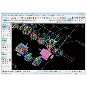
Aerospace CADPAC-CREATOR

Support for strength analysis in the aerospace field using 2D3D integrated design CAD.

In the aerospace industry, advanced strength analysis is essential to ensure the safety and reliability of products. In particular, the design of aircraft fuselages and components must withstand use in harsh environments. Inadequate design can lead to serious accidents. CADPAC-CREATOR integrates 2D and 3D data, making it easy to create and edit the shape data necessary for strength analysis. 【Usage Scenarios】 - Design of aircraft components - Structural design of spacecraft - Strength analysis simulation 【Benefits of Implementation】 - Reduced design time - Improved design quality - Cost reduction

  • cadpac-creator_02.png
  • 2D CAD machine
  • 3D CAD
  • Other CAD
  • soft

Added to bookmarks

Bookmarks list

Bookmark has been removed

Bookmarks list

You can't add any more bookmarks

By registering as a member, you can increase the number of bookmarks you can save and organize them with labels.

Free membership registration

Basic Knowledge of "3D Models" - How Can They Be Used Outside the Creative Field?

This book explains everything from the basics to actual use cases, including "digital twins" and "digital archives," which synchronize with the target objects and perform real-time analysis!

"3D models" have been utilized in creative fields such as games and animation (3DCG) as well as in engineering fields like design and manufacturing (3DCAD). However, due to the evolution of modeling software, improvements in hardware performance for processing 3D models, and the spread of VR and AR, they have started to be used in various other fields. [Overview of Basic Knowledge Materials] ■ What is a 3D model ■ Formats and characteristics of 3D models ■ The process of 3D modeling ■ Advantages of 3D models and case studies ■ List of equipment used ■ FAQ *For more details, please download the PDF or contact us directly.

  • 3D measuring device
  • soft

Added to bookmarks

Bookmarks list

Bookmark has been removed

Bookmarks list

You can't add any more bookmarks

By registering as a member, you can increase the number of bookmarks you can save and organize them with labels.

Free membership registration

NFTe, Inc. [3D CAD Implementation Case] i CAD SX

Simultaneously achieving the difficult balance of "shortening delivery times" and "reducing design defects" in 3D CAD.

We will introduce a case study of business improvement using the specialized 3D CAD "iCAD SX" for mechanical design. "NFT" is expanding its business in the design and manufacturing of precision molds for semiconductors, facing various issues due to the increasing complexity and shorter delivery times of the ordered equipment. Having previously experienced unsuccessful transitions to 3D design, the company prioritized "the performance of creating 3D models based on existing 2D drawing data" and selected "iCAD SX" from multiple 3D CAD options. As a result, they have not only reduced the occurrence of design defects associated with shorter delivery times and decreased the man-hours required to produce drawings, but they have also gained significant feedback as a presentation tool. [Main Effects of Implementation] - Man-hours required to produce drawings reduced by up to 20% - Reduction in design defects (zero defects in unit design) - Significant reduction in man-hours for interference checking [Download Materials] - Currently available for limited viewing on the special site. Please click the link below.    ▼▼▼ Click here ▼▼▼

Added to bookmarks

Bookmarks list

Bookmark has been removed

Bookmarks list

You can't add any more bookmarks

By registering as a member, you can increase the number of bookmarks you can save and organize them with labels.

Free membership registration

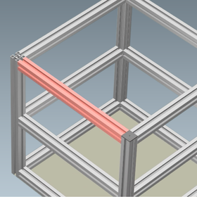
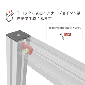
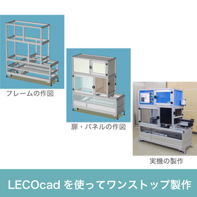
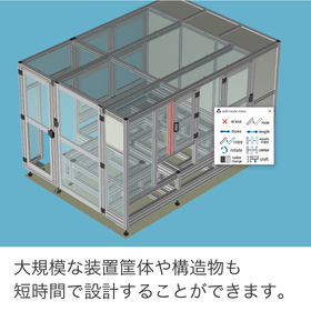
3D CAD 'LECOcad' for Designing Aluminum Frames for Fixtures

Furniture and fixture design made easier. Free 3D design software exclusively for RecoFrame.

In the furniture and fixture industry, product design that balances aesthetics and functionality is essential. Particularly for fixtures, efficient arrangement in limited spaces and flexibility to accommodate various uses are crucial. Additionally, ease of assembly and visual appeal are factors that enhance the product's value. LECOcad is a dedicated 3D design support software developed to streamline the process from the design of the Recoframe to material selection, estimation, and ordering, supporting the resolution of these challenges. 【Usage Scenarios】 - Design and planning of store fixtures - Structural design of exhibition booths - Modular design of office furniture - Prototyping and consideration of DIY furniture - Drafting structures that combine various accessories 【Benefits of Implementation】 - Reduction in design time - Streamlining of material selection - Centralization of estimation and ordering processes - Increased design flexibility - Visualization of the final image

Added to bookmarks

Bookmarks list

Bookmark has been removed

Bookmarks list

You can't add any more bookmarks

By registering as a member, you can increase the number of bookmarks you can save and organize them with labels.

Free membership registration

[Case Study of 3D CAD Software for Mechanical Design] Yushin Seiki Co., Ltd.

[Free Case Study Provided] Evolving extraction robot technology by utilizing 3D data for optimal design!

We would like to introduce a case where "iCAD SX" was implemented at Yushin Seiki Co., Ltd., which boasts advanced technology in robots for extracting plastic injection molded products. The product was introduced for its high speed, compatibility with past 2D drawing data, and the ability to quickly perform interference checks, weight, and center of gravity calculations. The design system responds swiftly to short delivery orders, and efficiency has been achieved not only in design operations but also in assembly processes and communication with customers. 【Case Overview】 ■Challenges - Balancing strength that withstands lightweight and high-speed operation ■Results - Improved efficiency in design operations - Enhanced design accuracy - Advanced utilization of 3D data *For more details, please refer to the PDF document or feel free to contact us.

Added to bookmarks

Bookmarks list

Bookmark has been removed

Bookmarks list

You can't add any more bookmarks

By registering as a member, you can increase the number of bookmarks you can save and organize them with labels.

Free membership registration

[Case Study of 3D CAD Software for Mechanical Design] Enshu Corporation

[Free Case Studies Available] Achieving a "Total Cost Reduction of 30%" through seamless integration from design to assembly with 3D models!

We would like to introduce a case study of the implementation of "iCAD SX" at Enshu Corporation, a major machine tool manufacturer. The company has developed a three-year plan to convert all design processes of FTL (Flexible Transfer Line) and FMS (Flexible Manufacturing System) into 3D. In the first year of transformation, 2D and 3D were integrated seamlessly, and the ultra-fast "iCAD SX Mechanical PRO" was actually applied to the design of the new system line, achieving significant results. [Case Overview] ■Challenges - Convert all design processes of FTL and FMS into 3D ■Results - 2D and 3D were integrated seamlessly - "iCAD SX Mechanical PRO" was actually applied to the design of the new system line *For more details, please refer to the PDF document or feel free to contact us.

Added to bookmarks

Bookmarks list

Bookmark has been removed

Bookmarks list

You can't add any more bookmarks

By registering as a member, you can increase the number of bookmarks you can save and organize them with labels.

Free membership registration

[Case Study of 3D CAD Software for Mechanical Design] Daiwa Seisakusho Co., Ltd.

[Free Case Study Provided] Established a system to utilize customer feedback in products using 3D models!

In addition to the development and sales of noodle-making machines, we would like to introduce a case where "iCAD SX" was implemented at Daiwa Seisakusho Co., Ltd., which supports the prosperity of its customers. The company, which values communication with everyone involved in noodle-making, has adopted our product as a new communication tool. They have strengthened their development system, developing and improving over 30 types of noodle-making machines with just five people, and have achieved results in process efficiency through team design. 【Case Overview】 ■Challenges - It is difficult to imagine the finished product by looking at 2D drawings. - Combining assemblies designed individually does not lead to optimal designs. ■Results - Established a system that allows customers to understand the design content before creating custom products. - Applied to the development of new products, establishing a system to reflect customer feedback in the products. *For more details, please refer to the PDF document or feel free to contact us.

Added to bookmarks

Bookmarks list

Bookmark has been removed

Bookmarks list

You can't add any more bookmarks

By registering as a member, you can increase the number of bookmarks you can save and organize them with labels.

Free membership registration

"Virtual factory and virtual real machine can be reproduced!" V-Eye (Virtual Eye)

[Recommended for design verification!] Realize a virtual reality space with 3D data! A product that allows you to experience actual work in a virtual space!

"V-Eye (Virtual Eye)" can recreate virtual factories and virtual machines right in front of you. It supports major 3D CAD data (such as CATIA, Solid Works, PRO-E, Inventor, etc.) and is compatible with various file extensions (such as STEP, IGES, STL, WRL, OBJ, 3dS, etc.). By combining general-purpose equipment, it achieves high reliability at a low cost. 【Features】 ■ Realizes a virtual reality space with 3D data ■ Achieves high reliability at a low cost through the combination of general-purpose equipment ■ Allows for collaborative work by two people (even from remote locations over a LAN) *For more details, please refer to the PDF materials or feel free to contact us.

  • simulator
  • Other industrial robots
  • Virtual Reality Related
  • soft

Added to bookmarks

Bookmarks list

Bookmark has been removed

Bookmarks list

You can't add any more bookmarks

By registering as a member, you can increase the number of bookmarks you can save and organize them with labels.

Free membership registration

Finishing Estimation Software [Neo Finishing] Case Study: Daishin Construction Co., Ltd.

It's been about 12 years since its introduction! The more I get used to it, the more I realize what a wonderful software it is!

We would like to introduce a case study of the finishing estimation software "Neo Finishing" implemented by Daijin Construction Co., Ltd. The company faced the challenge of improving the efficiency of its estimation operations at the time of implementation. It was essential for the estimation work to be completed in a short time, and a flexible system was desired. The simple and user-friendly system from Advantech perfectly met these expectations. About 12 years have passed since its implementation (as of November 2021), and both structural and finishing estimations can be linked to CAD data, resulting in a reduction in estimation time. Recently, we learned that we can create 3D models and perspectives based on CAD data drawn for estimation, and we would like to utilize this for sales support. 【Case Overview】 ■ Implementing Company: Daijin Construction Co., Ltd. (Naha City, Okinawa Prefecture) ■ Employee Scale: Less than 100 to 500 people ■ Implemented Software: Neo Finishing *For more details, please refer to the PDF document or feel free to contact us.

  • Software (middle, driver, security, etc.)
  • soft

Added to bookmarks

Bookmarks list

Bookmark has been removed

Bookmarks list

You can't add any more bookmarks

By registering as a member, you can increase the number of bookmarks you can save and organize them with labels.

Free membership registration

Nippon Steel Corporation [3D CAD Implementation Case] i CAD SX

Visualization of design! 3D CAD that realizes the advancement of work processes.

At "Nippon Steel & Sumitomo Metal Corporation Hiroshima Works," there were issues arising from changes in the design of large resin pellet manufacturing equipment (industrial machinery and plant facilities) that could not be covered by 2D planning drawings. The company decided to transition to 3D design with the aim of front-loading. After experiencing difficulties with a history-based 3D CAD that was not well established, they selected "iCAD SX," which does not suffer from slow response times even when handling tens of thousands of parts. As a result, they were able to enhance design reviews and disclose design information early using 3D models, leading to an advancement in the design workflow and cost reductions through the compactification of equipment. [Main Effects of Implementation] - Creation of overall planning drawings was halved (reduced from 2 months to less than 1 month) - Significant reduction in assembly interference and a 20% reduction in design support personnel - Cost reduction due to equipment compactification (e.g., 43% reduction in volume) [Download Materials] - Currently available for limited viewing on the special website. Please click the link below.

Added to bookmarks

Bookmarks list

Bookmark has been removed

Bookmarks list

You can't add any more bookmarks

By registering as a member, you can increase the number of bookmarks you can save and organize them with labels.

Free membership registration

Effortless 3D conversion that takes advantage of the strengths of both 2D and 3D.

This is an invitation to an online seminar aimed at those who are using 2D CAD and are wondering what changes would occur if they incorporated 3D design.

In recent years, overseas companies have achieved remarkable growth, and as you may know, global competition has become intense. Along with this, design tools have also been evolving. While it may be possible to design without any issues in 2D, there are likely some problems associated with relying solely on 2D design, such as: 1. Difficulty in accurately and quickly conveying complex 2D conceptual drawings and component information. 2. Challenges in detecting issues like interference, leading to rework and delays in delivery. 3. Increased time spent on creating and revising drawings with each iteration of design trial and error. However, many of you may be concerned about whether the transition from 2D design to 3D design can be smooth. In this seminar, we will cover: 1. The benefits of transitioning to 3D. 2. Intuitive 3D modeling with a 2D mindset. 3. Prevention of simple mistakes that occurred in 2D. 4. Things that are difficult in 2D becoming easy in 3D. 5. Effectively utilizing both 2D and 3D to enhance design quality. We will showcase a demonstration of 3D modeling that leverages 2D drawing assets, highlighting a "seamless transition to 3D" that takes advantage of the strengths of both 2D and 3D.

  • 3D CAD
  • 2D CAD machine
  • Other CAD
  • soft

Added to bookmarks

Bookmarks list

Bookmark has been removed

Bookmarks list

You can't add any more bookmarks

By registering as a member, you can increase the number of bookmarks you can save and organize them with labels.

Free membership registration