![[Analysis Case] Analysis of PTC Resin Heater](https://image.mono.ipros.com/public/product/image/737/2000060419/IPROS90029776198144513280.gif?w=280&h=280)
[Analysis Case] Analysis of PTC Resin Heater
Analyzing the property that electrical resistance increases as temperature rises.
PTC resin has the property of increasing electrical resistance as the temperature rises (temperature dependence). We conducted an analysis of a heater that utilizes this property. This heater has the characteristic that as the temperature rises, the inherent resistance of the PTC resin increases, limiting the current, so it does not exceed a certain temperature. We will perform a current distribution analysis when a voltage of 100[V] is applied to the electrode terminals of the heater. For more details, please download the catalog.
- Company:フォトン
- Price:Other
![[Analysis Case] Induction Heating Analysis of Steel Plates (Coupled Analysis of Magnetic Field and Heat)](https://image.mono.ipros.com/public/product/image/bc6/2000060423/IPROS57433509186211173817.gif?w=280&h=280)
![[Analysis Case] Stress Analysis of Elastic Bodies (Frequency Response)](https://image.mono.ipros.com/public/product/image/304/2000060433/IPROS58486156492191510475.jpeg?w=280&h=280)
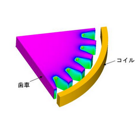
![[Case Study] Induction Heating for Gear Hardening](https://image.mono.ipros.com/public/product/image/0e3/2000060450/IPROS82546072155491411203.gif?w=280&h=280)


![[Analysis Case] Electromagnetic Field Analysis of Polyethylene-Filled Waveguides](https://image.mono.ipros.com/public/product/image/a52/2000763638/IPROS54400837570990680291.png?w=280&h=280)
![[Analysis Case] Input Impedance Analysis of a Dipole Antenna](https://image.mono.ipros.com/public/product/image/6cf/2000763652/IPROS40087588114269343573.png?w=280&h=280)
![[Case Study] Photonic Crystal Optical Waveguide (Electromagnetic Field Analysis)](https://image.mono.ipros.com/public/product/image/abe/2000763749/IPROS26662464443057788112.png?w=280&h=280)
![[Analysis Case] Analysis using automatic load condition setting function (TE wave, TM wave)](https://image.mono.ipros.com/public/product/image/250/2000763805/IPROS79396941278518386378.png?w=280&h=280)
![[Analysis Case] Magnetic Field Analysis of Gear Sensors](https://image.mono.ipros.com/public/product/image/962/2000763847/IPROS58205498186159764360.png?w=280&h=280)
![[Analysis Case] Magnetic Field Analysis of a Transformer](https://image.mono.ipros.com/public/product/image/33d/2000763861/IPROS67020261149595160001.png?w=280&h=280)