iPROS Manufacturing
  • Search for products by classification category

    • Electronic Components and Modules
      Electronic Components and Modules
      61672items
    • Machinery Parts
      Machinery Parts
      75918items
    • Manufacturing and processing machinery
      Manufacturing and processing machinery
      102035items
    • Scientific and Physics Equipment
      Scientific and Physics Equipment
      36334items
    • Materials
      Materials
      37774items
    • Measurement and Analysis
      Measurement and Analysis
      55153items
    • Image Processing
      Image Processing
      15366items
    • Control and Electrical Equipment
      Control and Electrical Equipment
      54559items
    • Tools, consumables, and supplies
      Tools, consumables, and supplies
      65596items
    • Design and production support
      Design and production support
      12662items
    • IT/Network
      IT/Network
      45646items
    • Office
      Office
      14182items
    • Business support services
      Business support services
      25345items
    • Seminars and Skill Development
      Seminars and Skill Development
      6558items
    • Pharmaceutical and food related
      Pharmaceutical and food related
      34161items
    • others
      75340items
  • Search for companies by industry

    • Manufacturing and processing contract
      7338
    • others
      4986
    • Industrial Machinery
      4445
    • Machine elements and parts
      3330
    • Other manufacturing
      2883
    • Trading company/Wholesale
      2650
    • IT/Telecommunications
      2571
    • Industrial Electrical Equipment
      2319
    • Building materials, supplies and fixtures
      1816
    • software
      1666
    • Electronic Components and Semiconductors
      1587
    • Resin/Plastic
      1500
    • Service Industry
      1478
    • Testing, Analysis and Measurement
      1130
    • Ferrous/Non-ferrous metals
      986
    • environment
      699
    • Chemical
      640
    • Automobiles and Transportation Equipment
      582
    • Printing Industry
      513
    • Information and Communications
      465
    • Consumer Electronics
      412
    • Energy
      332
    • Rubber products
      317
    • Food Machinery
      308
    • Optical Instruments
      279
    • robot
      273
    • fiber
      254
    • Paper and pulp
      230
    • Pharmaceuticals and Biotechnology
      173
    • Electricity, Gas and Water Industry
      167
    • Warehousing and transport related industries
      149
    • Glass and clay products
      139
    • Food and Beverage
      130
    • CAD/CAM
      124
    • retail
      108
    • Medical Devices
      107
    • Educational and Research Institutions
      107
    • Ceramics
      98
    • wood
      87
    • Transportation
      84
    • Petroleum and coal products
      63
    • Medical and Welfare
      62
    • Shipbuilding and heavy machinery
      51
    • Aviation & Aerospace
      48
    • Fisheries, Agriculture and Forestry
      41
    • equipment
      40
    • Materials
      33
    • Public interest/special/independent administrative agency
      31
    • Research and development equipment and devices
      29
    • Government
      24
    • self-employed
      24
    • Mining
      17
    • cosmetics
      15
    • Finance, securities and insurance
      14
    • Restaurants and accommodations
      10
    • Individual
      10
    • Police, Fire Department, Self-Defense Forces
      7
    • Laboratory Equipment and Consumables
      5
    • Raw materials for reagents and chemicals
      4
    • Contracted research
      3
  • Special Features
  • Ranking

    • Overall Products Ranking
    • Overall Company Ranking
Search for Products
  • Search for products by classification category

  • Electronic Components and Modules
  • Machinery Parts
  • Manufacturing and processing machinery
  • Scientific and Physics Equipment
  • Materials
  • Measurement and Analysis
  • Image Processing
  • Control and Electrical Equipment
  • Tools, consumables, and supplies
  • Design and production support
  • IT/Network
  • Office
  • Business support services
  • Seminars and Skill Development
  • Pharmaceutical and food related
  • others
Search for Companies
  • Search for companies by industry

  • Manufacturing and processing contract
  • others
  • Industrial Machinery
  • Machine elements and parts
  • Other manufacturing
  • Trading company/Wholesale
  • IT/Telecommunications
  • Industrial Electrical Equipment
  • Building materials, supplies and fixtures
  • software
  • Electronic Components and Semiconductors
  • Resin/Plastic
  • Service Industry
  • Testing, Analysis and Measurement
  • Ferrous/Non-ferrous metals
  • environment
  • Chemical
  • Automobiles and Transportation Equipment
  • Printing Industry
  • Information and Communications
  • Consumer Electronics
  • Energy
  • Rubber products
  • Food Machinery
  • Optical Instruments
  • robot
  • fiber
  • Paper and pulp
  • Pharmaceuticals and Biotechnology
  • Electricity, Gas and Water Industry
  • Warehousing and transport related industries
  • Glass and clay products
  • Food and Beverage
  • CAD/CAM
  • retail
  • Medical Devices
  • Educational and Research Institutions
  • Ceramics
  • wood
  • Transportation
  • Petroleum and coal products
  • Medical and Welfare
  • Shipbuilding and heavy machinery
  • Aviation & Aerospace
  • Fisheries, Agriculture and Forestry
  • equipment
  • Materials
  • Public interest/special/independent administrative agency
  • Research and development equipment and devices
  • Government
  • self-employed
  • Mining
  • cosmetics
  • Finance, securities and insurance
  • Restaurants and accommodations
  • Individual
  • Police, Fire Department, Self-Defense Forces
  • Laboratory Equipment and Consumables
  • Raw materials for reagents and chemicals
  • Contracted research
Special Features
Ranking
  • Overall Products Ranking
  • Overall Company Ranking
  • privacy policy
  • terms of service
  • About Us
  • Careers
  • Advertising
  1. Home
  2. Ferrous/Non-ferrous metals
  3. 松井製作所
  4. Product/Service List
Ferrous/Non-ferrous metals
  • Added to bookmarks

    Bookmarks list

    Bookmark has been removed

    Bookmarks list

    You can't add any more bookmarks

    By registering as a member, you can increase the number of bookmarks you can save and organize them with labels.

    Free membership registration

松井製作所

EstablishmentMarch 1961
capital3300Ten thousand
number of employees81
addressOsaka/Joto-ku, Osaka-shi/4-1-23 Nagata
phone06-6961-6043
  • Special site
  • Official site
last updated:Jun 26, 2026
松井製作所logo
  • Contact this company

    Inquiry Form
  • Before making an inquiry

    Download Profile
  • Company information
  • Products/Services(1770)
  • catalog(71)
  • news(22)

松井製作所 Product Lineup

  • category

136~180 item / All 1770 items

Displayed results

Filter by category
Forging Forging
Machining Machining
Pipe processing Pipe processing
Brazing process Brazing process
Assembly and Inspection Assembly and Inspection
Unit product Unit product
Others Others
YouTube YouTube
class="retina-image"

Lightweighting through hot forging for aerospace applications

Achieving lightweight aerospace components through hot forging!

In the aerospace industry, reducing the weight of aircraft is essential for improving fuel efficiency and reducing operational costs. Lightweighting components directly enhances the performance of the aircraft, necessitating technologies that can achieve weight reduction while maintaining high strength. Hot forging contributes to the lightweighting of aerospace components by maximizing the strength of metal materials while precisely shaping them. Our video materials explain the principles and characteristics of hot forging, improvement examples, and key points for selecting processing partners. Hot forging technology contributes to achieving both lightweighting and high performance in the aerospace field. 【Usage Scenarios】 * Aircraft components (engine parts, structural parts, etc.) * Space rocket components * Drone components 【Benefits of Implementation】 * Improved fuel efficiency through lightweighting of components * Ensured high strength and durability * Increased design flexibility

  • others

Added to bookmarks

Bookmarks list

Bookmark has been removed

Bookmarks list

You can't add any more bookmarks

By registering as a member, you can increase the number of bookmarks you can save and organize them with labels.

Free membership registration

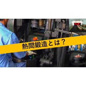
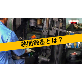
What is hot forging for automobiles?

Contributing to the improvement of automotive parts strength!

In the automotive industry, improving the strength of components is essential to achieve both safety and durability. Particularly in areas subjected to high loads, such as engine parts and suspension components, materials and processing methods with excellent strength are required. Hot forging contributes to the performance enhancement of automotive parts by shaping metal materials at high temperatures, imparting high strength and toughness. Our video materials explain the principles and characteristics of hot forging, examples of improvements, and key points for selecting processing partners. Learning about hot forging can help solve challenges in the design and manufacturing of automotive parts. 【Application Scenes】 * Engine parts * Suspension components * Safety-related parts 【Effects of Implementation】 * Improved component strength * Increased product reliability * Potential cost reduction

  • others

Added to bookmarks

Bookmarks list

Bookmark has been removed

Bookmarks list

You can't add any more bookmarks

By registering as a member, you can increase the number of bookmarks you can save and organize them with labels.

Free membership registration

Identify recall causes with a cause-and-effect diagram for the automotive industry!

Learn the basics of the cause-and-effect diagram and use it to help with recall measures!

In the automotive industry, it is important to investigate the causes of recalls and establish measures to prevent recurrence. In particular, quality issues can significantly undermine a company's trust, so prompt and accurate responses are required. The cause-and-effect diagram is an effective tool for systematically analyzing the causes of problems and identifying root causes. This video explains the basics of the cause-and-effect diagram and introduces how it can be utilized in recall measures. 【Utilization Scenes】 * Cause analysis during a recall * Identification of root causes of quality issues * Planning of recurrence prevention measures 【Effects of Introduction】 * Acceleration of problem-solving * Promotion of quality improvement * Restoration of customer trust

  • others

Added to bookmarks

Bookmarks list

Bookmark has been removed

Bookmarks list

You can't add any more bookmarks

By registering as a member, you can increase the number of bookmarks you can save and organize them with labels.

Free membership registration

Reduce defects with a cause-and-effect diagram for the manufacturing industry!

Explaining the basics of the cause-and-effect diagram! This is a video resource that helps in reducing defects.

In the manufacturing industry, the occurrence of defective products is a significant challenge that leads to increased costs and a loss of trust from customers. To reduce defects, it is essential to identify the root causes of the problems and implement countermeasures. This video explains how to create a cause-and-effect diagram (fishbone diagram), which is fundamental to quality management. The cause-and-effect diagram is a powerful tool for systematically analyzing the causes of problems and developing effective countermeasures. This video material will serve as the first step in problem-solving for those in the manufacturing industry aiming to reduce defects. 【Usage Scenarios】 * Analyzing the causes of defects in the manufacturing site * Improving the quality management system * Enhancing problem-solving capabilities 【Effects of Implementation】 * Reducing the defect occurrence rate * Streamlining quality management * Improving problem-solving abilities

  • others

Added to bookmarks

Bookmarks list

Bookmark has been removed

Bookmarks list

You can't add any more bookmarks

By registering as a member, you can increase the number of bookmarks you can save and organize them with labels.

Free membership registration

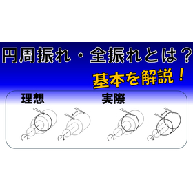
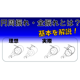
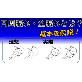
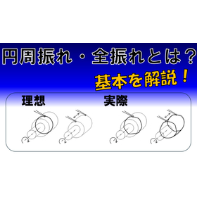
[For Shipbuilding] Geometric Tolerances: Explanation Video on Circular Runout and Total Runout

A must-see for ship designers! An explanation of geometric tolerances related to structural stability.

In the shipbuilding industry, accurate dimensions and shapes of components are crucial to ensure the strength and safety of the hull. Particularly for parts related to the structural stability of the hull, understanding geometric tolerances is essential. Geometric tolerances such as circular runout and total runout directly affect the assembly accuracy and performance of components, and improper management can lead to structural issues. This video explains the basics of a type of geometric tolerance known as "circular runout and total runout." 【Application Scenarios】 - Design of hull structural components - Quality control of welds - Inspection of machined parts 【Benefits of Implementation】 - Improved reliability of structures - Reduction of design errors - Increased efficiency in quality control

  • others

Added to bookmarks

Bookmarks list

Bookmark has been removed

Bookmarks list

You can't add any more bookmarks

By registering as a member, you can increase the number of bookmarks you can save and organize them with labels.

Free membership registration

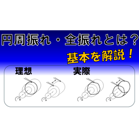
[For Optical Equipment] Explanation of Geometric Tolerances: Circular Runout and Total Runout

Explaining the basics of geometric tolerances that help maintain the performance of optical instruments!

In the optical equipment industry, understanding geometric tolerances is essential for maintaining product accuracy and reliability. Particularly in precision components such as lenses and mirrors, managing circular runout and total runout directly affects optical performance. If these tolerances are not properly managed, distortions can occur in light transmission and reflection, potentially leading to a decrease in equipment performance. This video explains the basics of "circular runout and total runout," which are types of geometric tolerances. 【Application Scenarios】 - Manufacturing optical lenses and mirrors - Designing precision measuring instruments - Quality control of optical systems 【Benefits of Introduction】 - Deepening understanding of geometric tolerances to improve design and manufacturing quality - Maintaining product performance and enhancing reliability - Reducing defective products and cutting costs

  • others

Added to bookmarks

Bookmarks list

Bookmark has been removed

Bookmarks list

You can't add any more bookmarks

By registering as a member, you can increase the number of bookmarks you can save and organize them with labels.

Free membership registration

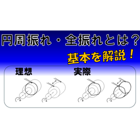
[For the watch industry] Geometric tolerance explanation video on circular runout and total runout.

Explaining the basics of geometric tolerances in watch manufacturing!

In the watch industry, precise processing of components is essential to achieve both product quality and luxury feel. Particularly in movements and exterior parts, not only dimensional accuracy but also geometric tolerances significantly affect the product's performance and appearance. Understanding geometric tolerances such as circular runout and total runout is a crucial factor in high-quality watch manufacturing. This video explains the basics of a type of geometric tolerance known as "circular runout and total runout," supporting problem-solving in watch manufacturing. 【Application Scenarios】 - Design and manufacturing of watch components - Education in quality control departments - Technical guidance for engineers 【Effects of Implementation】 - Deepening understanding of geometric tolerances, improving design and manufacturing quality - Reduction of defective products and cost savings - Skill enhancement for engineers

  • others

Added to bookmarks

Bookmarks list

Bookmark has been removed

Bookmarks list

You can't add any more bookmarks

By registering as a member, you can increase the number of bookmarks you can save and organize them with labels.

Free membership registration

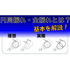
[For Electronic Devices] Geometric Tolerance Circular Runout and Total Runout Explanation Video

Contributing to the improvement of electronic equipment reliability! Explaining the basics of geometric tolerances.

In the electronics industry, accurate dimensions and shapes of components are crucial to ensure product reliability. Particularly in electronic devices exposed to vibrations and shocks, the runout of components can significantly affect product performance. Understanding circular runout and total runout is essential for setting appropriate tolerances during the design phase, leading to improved product quality. This video explains the basics of "circular runout and total runout," which are types of geometric tolerances. 【Application Scenarios】 - Design of electronic devices - Quality control - Education in manufacturing sites 【Effects of Implementation】 - Improved product reliability - Reduced defect rates - Streamlined design and manufacturing processes

  • others

Added to bookmarks

Bookmarks list

Bookmark has been removed

Bookmarks list

You can't add any more bookmarks

By registering as a member, you can increase the number of bookmarks you can save and organize them with labels.

Free membership registration

[For Robots] Geometric Tolerances: Circular Runout and Total Runout Basic Explanation

Contributing to the improvement of robot motion accuracy!

In the robotics industry, precise operation of products is essential. In particular, the precise movements of arms and joints are crucial factors that influence the quality and safety of the products. A lack of understanding of geometric tolerances can lead to design errors and manufacturing issues, potentially resulting in malfunctioning robots. This video explains the basics of a type of geometric tolerance known as "circular runout and total runout." By understanding the definitions of circular runout and total runout, how they are used in drawings, and the precautions to take when using them, you can contribute to improving the operational accuracy of robots. 【Application Scenarios】 - Design of robotic arms - Assembly of precision equipment - Training in quality control departments 【Benefits of Implementation】 - Improved operational accuracy of robots - Enhanced product quality - Problem-solving during design and manufacturing stages

  • others

Added to bookmarks

Bookmarks list

Bookmark has been removed

Bookmarks list

You can't add any more bookmarks

By registering as a member, you can increase the number of bookmarks you can save and organize them with labels.

Free membership registration

[For Semiconductor Manufacturing] Geometric Tolerances: Explanation Video on Circular Runout and Total Runout

Learn the basics of geometric tolerances in semiconductor manufacturing to improve yield!

In the semiconductor manufacturing industry, there is always a demand for improved product quality and yield. Particularly in areas where fine processing technology is crucial, the dimensional accuracy of components significantly affects product performance. A lack of understanding of geometric tolerances can lead to the occurrence of defective products and a decline in performance, potentially worsening yield. This video explains the basics of a type of geometric tolerance known as "circular runout and total runout," supporting the improvement of drawing interpretation skills. By watching this video, you can deepen your foundational knowledge of quality management in semiconductor manufacturing and potentially contribute to yield improvement. 【Usage Scenarios】 - Component design in semiconductor manufacturing - Education in quality control departments - Drawing interpretation on the manufacturing floor 【Effects of Implementation】 - Deepening understanding of geometric tolerances and improving drawing interpretation skills - Potential suppression of defective products and improvement in yield - Stabilization of product quality through enhanced knowledge of quality management

  • others

Added to bookmarks

Bookmarks list

Bookmark has been removed

Bookmarks list

You can't add any more bookmarks

By registering as a member, you can increase the number of bookmarks you can save and organize them with labels.

Free membership registration

[For Molds] Geometric Tolerance Circumferential Runout and Total Runout Explanation Video

Explaining the basic knowledge of geometric tolerances useful for mold design and manufacturing!

In the mold industry, dimensional accuracy is crucial to ensure product quality and durability. Particularly, understanding geometric tolerances is essential to prevent wear and deformation of molds. Improper management of circular runout and total runout can lead to early deterioration of molds and a decrease in product accuracy. This video explains the basics of "circular runout and total runout," which are types of geometric tolerances. 【Usage Scenarios】 - Mold design phase - Mold manufacturing process - Mold quality control 【Benefits of Introduction】 - Improvement in quality during mold design and manufacturing - Increased durability of molds - Reduction of defective products

  • others

Added to bookmarks

Bookmarks list

Bookmark has been removed

Bookmarks list

You can't add any more bookmarks

By registering as a member, you can increase the number of bookmarks you can save and organize them with labels.

Free membership registration

[For Precision Instruments] Geometric Tolerances: Circular Runout and Total Runout Basic Explanation

Contributing to the improvement of precision machinery quality!

In the precision machinery industry, high precision and reliability of products are essential. Particularly in the assembly and operation of fine components, understanding geometric tolerances becomes crucial. Improper management of circular runout and total runout can lead to deterioration in product performance or failure. This video explains the basics of "circular runout and total runout," which are types of geometric tolerances, including their definitions, usage examples, how they are represented in drawings, and points to be cautious about when using them. We hope this video will assist you in improving quality in the design and manufacturing of precision machinery. 【Application Scenarios】 - Design phase of precision machinery - Quality control in the manufacturing process - Performance evaluation of products 【Benefits of Introduction】 - Deepen understanding of geometric tolerances and improve quality in design and manufacturing - Contribute to enhancing product reliability - Reduce defective products and cut costs

  • others

Added to bookmarks

Bookmarks list

Bookmark has been removed

Bookmarks list

You can't add any more bookmarks

By registering as a member, you can increase the number of bookmarks you can save and organize them with labels.

Free membership registration

[For Medical Devices] Geometric Tolerance Circumferential Runout and Total Runout Explanation Video

Explaining the basics of geometric tolerances in the design and manufacturing of medical devices!

In the medical device industry, precise dimensions and shapes of components are required to ensure product safety. Particularly in medical devices that demand precise operation, even slight deviations in component dimensions can lead to malfunctions of the device or pose risks to patients. Understanding geometric tolerances, especially circular runout and total runout, is essential for ensuring quality during the design phase. This video will explain the definitions of circular runout and total runout, examples of their use, how they are represented in drawings, and precautions for their use. This will enable designers to create safer and more reliable medical devices. [Application Scenarios] - Design of medical devices - Manufacturing of medical devices - Quality control [Effects of Implementation] - Improvement in design quality - Reduction in defect rates during manufacturing processes - Enhancement of product safety

  • others

Added to bookmarks

Bookmarks list

Bookmark has been removed

Bookmarks list

You can't add any more bookmarks

By registering as a member, you can increase the number of bookmarks you can save and organize them with labels.

Free membership registration

Basic Explanation of Geometric Tolerances for Machine Tools: Circular Runout and Total Runout

Contributing to the improvement of precision in machine tools! Understanding circular runout and total runout.

In the machine tool industry, the precision of products is a crucial factor that affects quality. In particular, the runout of rotating parts directly impacts machining accuracy and can potentially reduce product performance and lifespan. Understanding circular runout and total runout is essential for solving these issues and producing high-quality products. This video explains the basics of geometric tolerances, specifically circular runout and total runout, and supports problem-solving in the design and manufacturing of machine tools. 【Usage Scenarios】 * Design and manufacturing of machine tools * Quality control of parts * Interpretation of drawings 【Benefits of Implementation】 * Enhanced understanding of geometric tolerances, leading to improved design and manufacturing precision * Improved ability to manage the quality of parts * Enhanced ability to interpret drawings, contributing to smoother communication

  • others

Added to bookmarks

Bookmarks list

Bookmark has been removed

Bookmarks list

You can't add any more bookmarks

By registering as a member, you can increase the number of bookmarks you can save and organize them with labels.

Free membership registration

[Aerospace] Geometric Tolerances: Circular Runout and Total Runout Explanation

Contributing to the improvement of precision machining quality!

In the aerospace industry, the reliability and safety of products are the most critical issues in precision machining. Particularly for products that require high precision, such as aircraft components, understanding geometric tolerances is essential. Improper management of circular runout and total runout can lead to performance degradation of parts and, in the worst case, accidents. This video explains the basics of "circular runout and total runout," which are types of geometric tolerances, and supports the improvement of quality control in precision machining. 【Usage Scenarios】 - Design and manufacturing of aerospace components - Manufacturing of precision mechanical parts - Education in quality control departments 【Benefits of Implementation】 - Deepening understanding of geometric tolerances and improving quality in design and manufacturing - Enhancing drawing interpretation skills - Reducing defective products and cutting costs

  • others

Added to bookmarks

Bookmarks list

Bookmark has been removed

Bookmarks list

You can't add any more bookmarks

By registering as a member, you can increase the number of bookmarks you can save and organize them with labels.

Free membership registration

[For Automotive Quality Management] Explanation of Geometric Tolerances: Circular Runout and Total Runout

Video materials useful for quality control of automotive parts!

In the automotive industry's quality control, the precise dimensions and shapes of parts are crucial factors that influence the safety and performance of products. Particularly for rotating and sliding components, managing circular runout and total runout is essential. If these geometric tolerances are not properly managed, it can lead to abnormal noises, vibrations, premature wear, and even serious malfunctions. This video explains the basics of "circular runout and total runout," which are types of geometric tolerances. By understanding the definitions of circular runout and total runout, how they are used in drawings, and the precautions to take when using them, you can contribute to solving challenges in quality control. 【Usage Scenarios】 - Design and manufacturing departments of automotive parts - Quality control departments - Technical communication with suppliers 【Benefits of Implementation】 - Deepen understanding of geometric tolerances, contributing to early detection and countermeasures for quality issues - Improve drawing interpretation skills - Enhance the skills of quality control personnel

  • others

Added to bookmarks

Bookmarks list

Bookmark has been removed

Bookmarks list

You can't add any more bookmarks

By registering as a member, you can increase the number of bookmarks you can save and organize them with labels.

Free membership registration

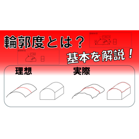
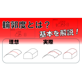
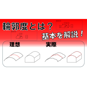
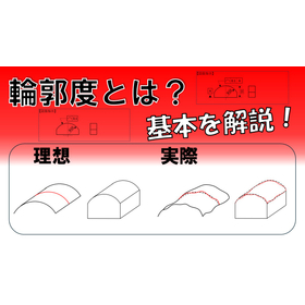
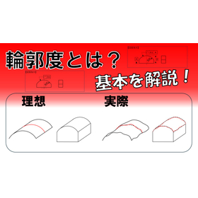
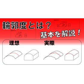
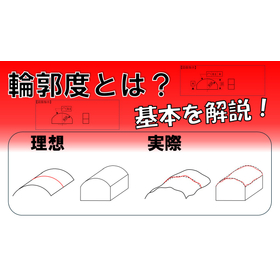
What is contour accuracy for measuring instruments? An explanation of the basics!

A clear explanation of the basics of contouring in a video!

In the measurement equipment industry, a precise understanding of geometric tolerances on drawings is essential to guarantee the accuracy of products. In particular, contour accuracy is a crucial factor in evaluating the shape precision of products, and understanding its definition and application methods is indispensable for quality management in design and manufacturing. A lack of understanding of contour accuracy can lead to incorrect measurements and the occurrence of defective products. This video explains the definition of contour accuracy, examples of its use, how it is applied on drawings, and points to be cautious about when using it. By learning the fundamentals of contour accuracy, you will contribute to improving quality in the design and manufacturing of measurement equipment. 【Usage Scenarios】 - Reading drawings in the design and manufacturing of measurement equipment - Promoting understanding of geometric tolerances among quality management personnel - Educational tool for engineers 【Benefits of Implementation】 - Improved quality in design and manufacturing through accurate understanding of contour accuracy - Enhanced drawing interpretation skills - Reduction of quality issues

  • others

Added to bookmarks

Bookmarks list

Bookmark has been removed

Bookmarks list

You can't add any more bookmarks

By registering as a member, you can increase the number of bookmarks you can save and organize them with labels.

Free membership registration

What is contouring for 3D printing? An explanation of the basics!

Resolving doubts about contour accuracy in 3D printing!

In the 3D printing industry, the quality of printed objects is extremely important. Particularly for parts and products that require dimensional accuracy, understanding contour accuracy is essential. If contour accuracy is not properly managed, the shape of the printed object may differ from the design, potentially leading to functional failures or assembly issues. This video explains the basics of "contour accuracy," a type of geometric tolerance, and supports quality improvement in 3D printing. 【Usage Scenarios】 - When producing prototypes with a 3D printer - When wanting to improve the dimensional accuracy of final products - When wanting to understand contour accuracy indications in design drawings 【Benefits of Implementation】 - Improved quality of printed objects - Realization of shapes as intended in the design - Reduction of defective products - Cost reduction

  • others

Added to bookmarks

Bookmarks list

Bookmark has been removed

Bookmarks list

You can't add any more bookmarks

By registering as a member, you can increase the number of bookmarks you can save and organize them with labels.

Free membership registration

What is contouring for robotics? An explanation of the basics!

Contributing to the improvement of robot motion accuracy!

In the field of robotics, precise movement of robots is required. Particularly in robots that perform assembly of parts or precision tasks, the shape accuracy of the components significantly affects operational precision. Understanding contour accuracy is essential for accurately interpreting instructions on drawings and improving the operational precision of robots. This video explains the basics of "contour accuracy," which is a type of geometric tolerance. 【Application Scenarios】 - Precise positioning of robotic arms - Accurate assembly of parts - Installation of sensors and cameras 【Effects of Introduction】 - Improvement in robot operational precision - Reduction of defective products - Enhancement of work efficiency

  • others

Added to bookmarks

Bookmarks list

Bookmark has been removed

Bookmarks list

You can't add any more bookmarks

By registering as a member, you can increase the number of bookmarks you can save and organize them with labels.

Free membership registration

What is contour accuracy for machine tools? An explanation of the basics!

Here are hints for improving processing accuracy!

In the machine tool industry, the machining accuracy that affects product quality is extremely important. Particularly when complex shapes or high-precision machining is required, understanding contour accuracy is essential. If contour accuracy is not properly indicated, it may lead to machining defects or a decline in product performance. This video explains the basics of "contour accuracy," which is a type of geometric tolerance. By understanding the definition of contour accuracy, examples of its use, how it is represented on drawings, and points to consider when using it, you can contribute to improving machining accuracy. 【Usage Scenarios】 - Design and manufacturing of machine tools - Creation and interpretation of machining drawings - Quality control 【Effects of Implementation】 - Improvement of machining accuracy - Reduction of defective products - Stabilization of product quality

  • others

Added to bookmarks

Bookmarks list

Bookmark has been removed

Bookmarks list

You can't add any more bookmarks

By registering as a member, you can increase the number of bookmarks you can save and organize them with labels.

Free membership registration

What is contouring for semiconductor manufacturing? An explanation of the basics!

I will answer the question, 'What is contouring?'

In the semiconductor manufacturing industry, there is a constant demand for improving product quality and yield. Particularly, as microfabrication technology advances, the shape accuracy of components becomes a crucial factor that affects product performance. A lack of understanding of contour accuracy can lead to errors during the design and manufacturing stages, potentially resulting in decreased yield. This video aims to contribute to quality management and yield improvement in semiconductor manufacturing by explaining the basics of "contour accuracy," a type of geometric tolerance. 【Usage Scenarios】 - Design and manufacturing of components in semiconductor manufacturing - Reading drawings in quality control departments - Problem-solving related to shape accuracy on the manufacturing floor 【Benefits of Implementation】 - Deepening understanding of contour accuracy to reduce mistakes during the design and manufacturing stages - Early detection of issues related to shape accuracy to improve yield - Enhancing product quality and increasing customer satisfaction

  • others

Added to bookmarks

Bookmarks list

Bookmark has been removed

Bookmarks list

You can't add any more bookmarks

By registering as a member, you can increase the number of bookmarks you can save and organize them with labels.

Free membership registration

What is contour accuracy for electronic devices? An explanation of the basics!

A must-see for electronic device designers! An explanation of the basics of contouring.

In the electronics industry, there is a demand for miniaturization and high precision of products. Since the dimensional accuracy of components affects the performance of the products, understanding geometric tolerances is essential. In particular, understanding contour tolerance is important for ensuring the shape accuracy of components and enhancing the reliability of products. This video will explain the definition of contour tolerance, examples of its use, how it is represented in drawings, and points to consider when using it. By deepening the understanding of contour tolerance, we contribute to improving design quality. 【Application Scenarios】 - Design of electronic devices - Creation of component drawings - Quality control 【Effects of Introduction】 - Deepen understanding of contour tolerance and improve design quality - Enhance drawing interpretation skills - Ensure shape accuracy of components and improve product reliability

  • others

Added to bookmarks

Bookmarks list

Bookmark has been removed

Bookmarks list

You can't add any more bookmarks

By registering as a member, you can increase the number of bookmarks you can save and organize them with labels.

Free membership registration

What is contour accuracy for precision instruments? An explanation of the basics!

Video materials useful for performance assurance of precision machinery.

In the precision machinery industry, the accurate shape and dimensions of products significantly affect performance. Particularly for high-precision components, understanding contour accuracy is essential. Improper interpretation or instruction regarding contour accuracy can lead to decreased product performance and the occurrence of defective products. This video explains the basics of "contour accuracy," a type of geometric tolerance. It covers the definition of contour accuracy, examples of its use, how it is represented on drawings, and points to consider when using it. This video will be beneficial for those involved in the design, manufacturing, and quality control of precision machinery, aiding in the assurance of product performance. 【Usage Scenarios】 - Creating drawings during the design phase of precision machinery - Quality control in manufacturing environments - Evaluating product performance 【Benefits of Implementation】 - Deepening understanding of contour accuracy and improving drawing interpretation accuracy - Enhancing product quality and reducing defect rates - Streamlining design and manufacturing processes

  • others

Added to bookmarks

Bookmarks list

Bookmark has been removed

Bookmarks list

You can't add any more bookmarks

By registering as a member, you can increase the number of bookmarks you can save and organize them with labels.

Free membership registration

Improving Quality with Contour Degree Explanation Video for Medical Devices

To those involved in the design and manufacturing of medical devices.

In the medical device industry, the safety and reliability of products are the top priorities. Since the shape accuracy of components affects the performance and safety of the products, understanding geometric tolerances is essential. Understanding contour tolerance leads to quality assurance in the design phase and a reduction in defect rates during the manufacturing process. This video explains the definition of contour tolerance, examples of its use, how it is applied in drawings, and points to note, supporting problem-solving in design and manufacturing. 【Usage Scenarios】 - Design of medical devices - Quality control in manufacturing departments - Specification confirmation during parts procurement 【Effects of Implementation】 - Improved drawing interpretation skills - Early detection of issues related to shape - Ensured reliability through quality improvement

  • others

Added to bookmarks

Bookmarks list

Bookmark has been removed

Bookmarks list

You can't add any more bookmarks

By registering as a member, you can increase the number of bookmarks you can save and organize them with labels.

Free membership registration

What is geometric tolerance for mold manufacturing? An explanation of the basics!

Explaining the basics of dimension management in mold manufacturing!

In the mold manufacturing industry, it is required to achieve dimensional accuracy according to the specifications in the drawings to ensure product quality. In particular, the contour shape of the mold significantly affects the finished product, making the understanding of contour accuracy and appropriate instructions crucial. Insufficient understanding of contour accuracy can lead to misinterpretation of drawings and manufacturing issues. This video explains the basics of "contour accuracy," which is a type of geometric tolerance. By knowing the definition of contour accuracy and understanding how it is indicated on drawings, it can help improve the precision of dimensional management in mold manufacturing. 【Application Scenarios】 - Interpretation of drawings in mold design - Dimensional measurement in mold manufacturing - Inspection in quality control 【Benefits of Introduction】 - Accurate understanding of drawing instructions - Improvement in quality during the manufacturing process - Reduction of defective products

  • others

Added to bookmarks

Bookmarks list

Bookmark has been removed

Bookmarks list

You can't add any more bookmarks

By registering as a member, you can increase the number of bookmarks you can save and organize them with labels.

Free membership registration

Basic Explanation Video on Contour Measurement for Machine Manufacturing

Deepen understanding of drawings and contribute to cost reduction!

In the mechanical manufacturing industry, product quality and cost management are important challenges. Accurately understanding geometric tolerances on drawings enhances the manufacturing precision of parts, suppresses the occurrence of defective products, and ultimately leads to cost reduction. A lack of understanding of contour tolerance can cause design changes and manufacturing issues, potentially resulting in unnecessary costs. This video explains the basics of contour tolerance and supports the improvement of drawing interpretation skills. 【Usage Scenarios】 - Quality control in the manufacturing process of parts - Checking drawings during design changes - Quality improvement for cost reduction 【Effects of Implementation】 - Improved drawing comprehension - Reduced defect rates - Contribution to cost reduction

  • others

Added to bookmarks

Bookmarks list

Bookmark has been removed

Bookmarks list

You can't add any more bookmarks

By registering as a member, you can increase the number of bookmarks you can save and organize them with labels.

Free membership registration

What is geometric tolerance contour for aerospace applications?

Deepen the understanding of contouring in the aerospace field!

In the aerospace industry, high precision of parts is required. Especially for components related to the safety of aircraft, it is important to maintain the shape as per the design drawings. A lack of understanding of contour tolerance can lead to manufacturing errors and performance degradation of parts. This video explains the basics of "contour tolerance," which is a type of geometric tolerance. It covers the definition of contour tolerance, examples of its use, how it is represented on drawings, and points to consider when using it. We hope this video will help improve the precision of parts in the aerospace field. 【Application Scenarios】 - Design and manufacturing of aircraft parts - Design and manufacturing of space development-related components - Quality control of parts that require high precision 【Benefits of Introduction】 - Improved drawing interpretation skills - Enhanced manufacturing precision of parts - Increased efficiency in quality control

  • others

Added to bookmarks

Bookmarks list

Bookmark has been removed

Bookmarks list

You can't add any more bookmarks

By registering as a member, you can increase the number of bookmarks you can save and organize them with labels.

Free membership registration

What is contouring for automotive quality management? An explanation of the basics!

Video materials useful for quality control of automotive parts.

In the automotive industry's quality management, the accurate shape and dimensions of parts influence the safety and performance of products. In particular, contour accuracy is an important factor in evaluating the shape precision of parts and is essential for verifying whether they are manufactured according to design drawings. A lack of understanding of contour accuracy can lead to defects in parts or assembly issues, ultimately resulting in a decline in product quality. This video explains the basics of "contour accuracy," a type of geometric tolerance. It covers the definition of contour accuracy, examples of its use, how it is represented on drawings, and points to consider when using it. Please use this video as a reference to assist in the quality management of automotive parts. 【Application Scenarios】 - Automotive parts design and manufacturing departments - Quality management departments - Technical education 【Benefits of Implementation】 - Deepening understanding of contour accuracy and improving drawing interpretation skills - Early detection of issues related to the shape precision of parts - Streamlining the quality management process - Enhancing product quality

  • others

Added to bookmarks

Bookmarks list

Bookmark has been removed

Bookmarks list

You can't add any more bookmarks

By registering as a member, you can increase the number of bookmarks you can save and organize them with labels.

Free membership registration

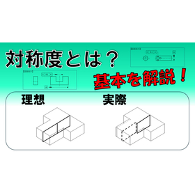
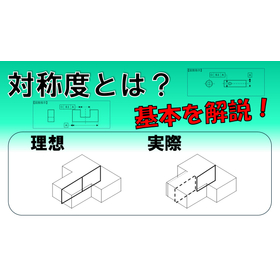
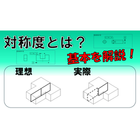
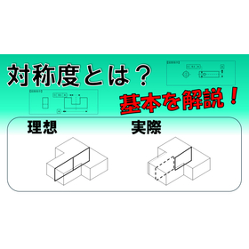
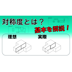
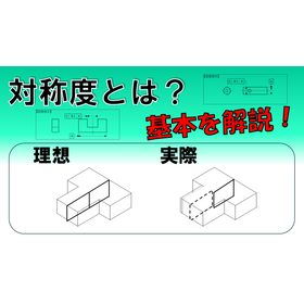
Video explanation of geometric tolerances for instrument manufacturing: symmetry.

Contributing to the improvement of musical instrument sound quality! Explaining the basics of symmetry.

In the musical instrument manufacturing industry, uniformity and stability of sound quality are required. In particular, for parts related to the vibration and resonance of instruments, the accuracy of dimensions significantly affects the timbre. Understanding symmetry is essential for ensuring quality at the design stage. Improper symmetry can lead to pitch discrepancies and deterioration of sound quality. This video explains the basics of "symmetry," a type of geometric tolerance. 【Application Scenarios】 - Design of instrument parts - Quality control in the manufacturing process - Problem-solving related to sound quality 【Effects of Implementation】 - Improvement of quality at the design stage - Reduction of defect rates in the manufacturing process - Stabilization of sound quality

  • others

Added to bookmarks

Bookmarks list

Bookmark has been removed

Bookmarks list

You can't add any more bookmarks

By registering as a member, you can increase the number of bookmarks you can save and organize them with labels.

Free membership registration

What is geometric tolerance for symmetry in watch manufacturing?

Explaining the "symmetry" that affects the aesthetics of watch parts!

In the watch manufacturing industry, precise processing of parts is required to balance the aesthetics and functionality of products. Particularly for external components such as watch dials and hands, symmetry greatly influences the quality of the product. Deficiencies in symmetry can lead to uneven appearances and decreased assembly accuracy, potentially compromising the product's value. This video explains the basics of "symmetry," a type of geometric tolerance. By understanding the definition of symmetry, examples of its use, how it is represented in drawings, and points to consider when using it, you can enhance the quality of design and manufacturing of watch components. 【Application Scenarios】 - Design and manufacturing of external components such as watch dials, hands, and cases - Quality control regarding the symmetry of parts - Understanding and utilizing drawing specifications 【Benefits of Implementation】 - Deepening understanding of symmetry to improve design and manufacturing quality - Balancing aesthetics and functionality of external components - Reducing defective products and cutting costs

  • others

Added to bookmarks

Bookmarks list

Bookmark has been removed

Bookmarks list

You can't add any more bookmarks

By registering as a member, you can increase the number of bookmarks you can save and organize them with labels.

Free membership registration

Basic Explanation of Geometric Tolerances for Optical Equipment: Symmetry

Contributing to the improvement of optical equipment performance! Explaining the basics of symmetry.

In the optical equipment industry, high precision is required in the design of lenses and housings. In particular, misalignment of the optical axis and errors in the arrangement of components can directly affect optical performance, potentially leading to deterioration in product image quality and a decline in performance. This video explains the basics of "symmetry," a type of geometric tolerance, and supports problem-solving in optical equipment design. By deepening the understanding of symmetry, it is possible to improve design accuracy and contribute to enhanced product performance. 【Usage Scenarios】 - Design of optical components such as lenses and mirrors - Design of optical equipment housings - Quality control in the manufacturing process 【Effects of Introduction】 - Improvement in design accuracy - Enhancement of product performance - Streamlining of quality control

  • others

Added to bookmarks

Bookmarks list

Bookmark has been removed

Bookmarks list

You can't add any more bookmarks

By registering as a member, you can increase the number of bookmarks you can save and organize them with labels.

Free membership registration

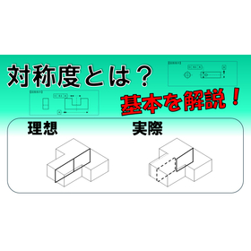
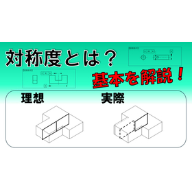
Basic explanatory video on geometric tolerances for electronic devices: symmetry.
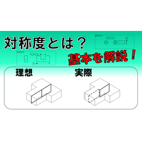
Helpful for designing electronic devices! An explanation of the basics of symmetry.

In the electronics industry, there is a demand for miniaturization and high precision of products. Understanding geometric tolerances at the design stage is essential for ensuring product quality and reliability. In particular, understanding symmetry is important for optimizing the arrangement and functionality of components. Improper tolerance settings can lead to decreased product performance and manufacturing issues. This video explains the basics of "symmetry," a type of geometric tolerance. 【Application Scenarios】 - Design of electronic devices - Creation of component drawings - Quality control 【Benefits of Implementation】 - Reduction of design errors - Improvement of product quality - Reduction of manufacturing costs
  • others

Added to bookmarks

Bookmarks list

Bookmark has been removed

Bookmarks list

You can't add any more bookmarks

By registering as a member, you can increase the number of bookmarks you can save and organize them with labels.

Free membership registration

What is symmetry in geometric tolerances for robotics?

Contributing to the stability of robot movements! Explaining the basics of symmetry.

In the field of robotics, precise movement and stability of robots are required. Particularly for robots that perform precise positioning and repetitive actions, the geometric tolerances of components significantly affect operational accuracy. Understanding symmetry is essential in the design, manufacturing, and maintenance of robots. This video explains the basics of "symmetry," a type of geometric tolerance. 【Application Scenes】 - Joints of robotic arms - Assembly of precision machinery - Installation of sensors and cameras 【Benefits of Introduction】 - Improved operational accuracy of robots - Enhanced product quality - Problem-solving during design and manufacturing stages - Improved maintainability

  • others

Added to bookmarks

Bookmarks list

Bookmark has been removed

Bookmarks list

You can't add any more bookmarks

By registering as a member, you can increase the number of bookmarks you can save and organize them with labels.

Free membership registration

【For Machine Tools】Geometric Tolerance Symmetry Basic Explanation Video

Explaining the basics of symmetry! It is useful for high-precision machining.

In the machine tool industry, high-precision parts processing is required. Particularly when micron-level precision is demanded, understanding symmetry is essential. If symmetry is not properly indicated, it can lead to assembly defects and performance degradation. This video explains the basics of "symmetry," which is a type of geometric tolerance. [Usage Scenarios] - Sites engaged in high-precision parts processing - Engineers who want to interpret drawings and provide appropriate indications - Those who want to learn the definition and usage of symmetry [Benefits of Introduction] - Deepens understanding of symmetry and improves drawing interpretation skills - Contributes to achieving high-precision parts processing - Enhances quality and reduces defect rates

  • others

Added to bookmarks

Bookmarks list

Bookmark has been removed

Bookmarks list

You can't add any more bookmarks

By registering as a member, you can increase the number of bookmarks you can save and organize them with labels.

Free membership registration

Basic Explanation of Geometric Tolerances for Semiconductor Manufacturing: Symmetry

Deepening the understanding of symmetry in microfabrication!

In the semiconductor manufacturing industry, particularly in fine processing, the precision of products greatly affects quality. Symmetry is essential for the accurate positioning and shape maintenance of fine processing components, and understanding it leads to a reduction in defective products and an improvement in yield. Understanding the definition of symmetry, its usage in drawings, and precautions for use contributes to the manufacturing of high-quality products. This video explains the basics of "symmetry," a type of geometric tolerance. 【Application Scenarios】 * Design and manufacturing of fine processing components * Quality control in semiconductor manufacturing processes * Improvement of drawing interpretation skills 【Effects of Introduction】 * Acquisition of knowledge about symmetry * Improvement of drawing comprehension skills * Enhancement of quality management capabilities

  • others

Added to bookmarks

Bookmarks list

Bookmark has been removed

Bookmarks list

You can't add any more bookmarks

By registering as a member, you can increase the number of bookmarks you can save and organize them with labels.

Free membership registration

Basic Explanation of Geometric Tolerances for Molds: Symmetry

Explaining the basics of symmetry that are useful for mold design and manufacturing!

In the mold industry, it is important to manufacture molds with precision according to the drawings in order to enhance the durability of the products. In particular, symmetry has a significant impact on the strength and functionality of the mold, making its understanding essential. If the symmetry specifications are not appropriate, it may lead to early mold failure or a decrease in product accuracy. This video explains the basics of "symmetry," which is a type of geometric tolerance. 【Application Scenarios】 - During the design phase of molds - Quality control during mold manufacturing - When interpreting drawings 【Effects of Implementation】 - Deepening the understanding of symmetry and improving the accuracy of mold design - Streamlining quality control in mold manufacturing - Reducing mold-related issues through accurate understanding of drawing specifications

  • others

Added to bookmarks

Bookmarks list

Bookmark has been removed

Bookmarks list

You can't add any more bookmarks

By registering as a member, you can increase the number of bookmarks you can save and organize them with labels.

Free membership registration

Explaining the basics of symmetry for medical devices!

To those involved in the design and manufacturing of medical devices.

In the medical device industry, the safety and reliability of products are of utmost importance. Accurate manufacturing of parts directly affects the performance of the devices and is closely linked to patient safety. Understanding geometric tolerances is essential for the precise interpretation of design drawings and is crucial for ensuring product quality. This video explains the basics of "symmetry," a type of geometric tolerance, and supports problem-solving in the design and manufacturing of medical devices. 【Application Scenarios】 - Design of medical devices - Quality control in manufacturing - Interpretation of drawings 【Benefits of Implementation】 - Accurate understanding of drawings, reducing design errors - Improved quality control capabilities in the manufacturing process - Enhanced product safety

  • others

Added to bookmarks

Bookmarks list

Bookmark has been removed

Bookmarks list

You can't add any more bookmarks

By registering as a member, you can increase the number of bookmarks you can save and organize them with labels.

Free membership registration

[For Precision Machinery] Geometric Tolerance Symmetry Basic Explanation Video

Learn the basics of symmetry and apply them to quality control!

In the precision machinery industry, understanding geometric tolerances on drawings is essential for ensuring product accuracy. In particular, understanding symmetry is crucial for the precise positioning and assembly of parts, directly impacting the performance and reliability of the product. Misunderstanding symmetry can lead to defective parts or assembly errors, potentially compromising the quality of the final product. This video explains the basics of "symmetry," a type of geometric tolerance. It covers the definition of symmetry, examples of its use, how it is represented on drawings, and points to consider when using it, addressing the challenges faced by quality management personnel. 【Application Scenarios】 - Quality management in the manufacturing of precision machine parts - Improvement of drawing interpretation skills - Management of product accuracy 【Benefits of Introduction】 - Deepens understanding of symmetry and enhances drawing interpretation abilities. - Contributes to improved product quality. - Leads to a reduction in defective products.

  • others

Added to bookmarks

Bookmarks list

Bookmark has been removed

Bookmarks list

You can't add any more bookmarks

By registering as a member, you can increase the number of bookmarks you can save and organize them with labels.

Free membership registration

[Aerospace] Geometric Tolerance Symmetry Basic Explanation Video

Explaining the basics of symmetry in a video!

In the aerospace industry, reducing the weight of products is essential for improving fuel efficiency and performance. Understanding and applying geometric tolerances correctly during the design phase is important for ensuring both weight reduction and product reliability. A lack of understanding of symmetry can lead to manufacturing errors in parts, potentially adversely affecting the performance of the final product. This video explains the basics of "symmetry," a type of geometric tolerance. It covers the definition of symmetry, examples of its use, how it is represented in drawings, and points to consider when using it. By watching this video, designers will be able to understand symmetry correctly and apply it in their designs. [Application Scenarios] - Design of aerospace components - Quality control in manufacturing processes - Technical education [Benefits of Introduction] - Reducing errors during the design phase - Improving quality in manufacturing processes - Enhancing the knowledge of engineers

  • others

Added to bookmarks

Bookmarks list

Bookmark has been removed

Bookmarks list

You can't add any more bookmarks

By registering as a member, you can increase the number of bookmarks you can save and organize them with labels.

Free membership registration

Basic Explanation of Geometric Tolerances for Symmetry in the Automotive Industry

Contributing to the improvement of precision in automotive parts!

In the automotive industry, high precision is required to ensure the quality and performance of parts. This is especially true for critical components such as engines and transmissions, where a precise understanding of symmetry and appropriate instructions are essential. Misinterpretation or incorrect instructions regarding symmetry can lead to functional failures or performance degradation of parts. This video explains the basics of "symmetry," a type of geometric tolerance, and supports problem-solving in the design and manufacturing of automotive parts. It covers the definition of symmetry, examples of use, how it is represented in drawings, and points to note when using it. [Application Scenarios] - Design of automotive parts - Quality control in manufacturing - Training for engineers [Benefits of Implementation] - Improvement in part quality - Reduction of design errors - Skill enhancement for engineers

  • others

Added to bookmarks

Bookmarks list

Bookmark has been removed

Bookmarks list

You can't add any more bookmarks

By registering as a member, you can increase the number of bookmarks you can save and organize them with labels.

Free membership registration

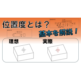
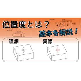
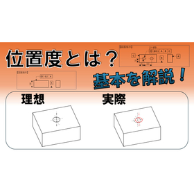
Positioning Explanation Video for Watch Manufacturing

Explaining the basics of positional accuracy! Improving quality in watch manufacturing.

In the watch manufacturing industry, precise positioning of components is essential to ensure product durability. Particularly in the case of intricate movements and exterior parts, the positional accuracy of each component significantly impacts the product's lifespan and performance. A lack of understanding of positional tolerances or improper instructions can lead to assembly defects or functional failures. This video explains the basics of "position tolerance," a type of geometric tolerance. It covers the definition of position tolerance, examples of its use, how it is represented in drawings, and points to consider when using it. Understanding the importance of position tolerance in watch manufacturing will help improve quality. 【Usage Scenarios】 - Manufacturing movement components - Assembling exterior parts - Education in quality control departments 【Benefits of Implementation】 - Improved assembly accuracy of components - Enhanced product durability - Reduction of defective products - Increased quality management capabilities

  • others

Added to bookmarks

Bookmarks list

Bookmark has been removed

Bookmarks list

You can't add any more bookmarks

By registering as a member, you can increase the number of bookmarks you can save and organize them with labels.

Free membership registration

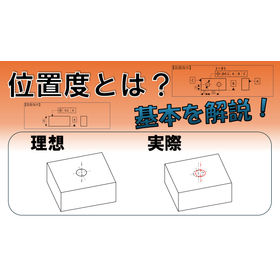
What is positional accuracy for optical devices? An explanation of the basics!

I will answer the question, 'What is positionality?'

In the optical equipment industry, precise positioning of components is required to maintain product performance. Particularly with precision parts such as lenses and sensors, even slight deviations in positioning can lead to a decline in optical performance. Improper positioning can cause image distortion and reduced resolution. This video explains the basics of "position tolerance," a type of geometric tolerance. By understanding the definition of position tolerance, how it is used in drawings, and points to be aware of, it can contribute to quality improvement in the design and manufacturing of optical equipment. 【Application Scenarios】 - Positioning of optical lenses - Installation of sensors - Assembly of precision parts 【Benefits of Implementation】 - Improvement of optical performance - Enhancement of product quality - Improvement of yield

  • others

Added to bookmarks

Bookmarks list

Bookmark has been removed

Bookmarks list

You can't add any more bookmarks

By registering as a member, you can increase the number of bookmarks you can save and organize them with labels.

Free membership registration

Video explaining positional accuracy for 3D printing

Deepen your understanding of positional accuracy in 3D printing!

In the 3D printing industry, the accuracy of the printed objects greatly affects the quality of the products. This is especially true when combining multiple parts or when products require precise movements, making the understanding of positional tolerance essential. Misunderstandings or inaccurate interpretations of positional tolerance can lead to defects in the printed objects or assembly failures. This video explains the basics of "positional tolerance," a type of geometric tolerance. It covers the definition of positional tolerance, examples of its use, how it is represented in drawings, and points to be cautious about when using it. Please make use of this information to produce high-quality printed objects with your 3D printer. 【Usage Scenarios】 - When manufacturing precision parts with a 3D printer - During the design and manufacturing of products that combine multiple parts - When conducting quality control of printed objects 【Benefits of Implementation】 - Deepening the understanding of positional tolerance and improving the accuracy of printed objects - Reducing mistakes during the design and manufacturing stages - Ensuring a stable supply of high-quality products

  • others

Added to bookmarks

Bookmarks list

Bookmark has been removed

Bookmarks list

You can't add any more bookmarks

By registering as a member, you can increase the number of bookmarks you can save and organize them with labels.

Free membership registration

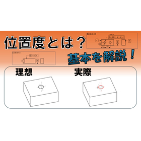
Positioning Accuracy Explanation Video for Electronic Devices

"What is positional degree?" I will answer that!

In the electronics industry, as products become smaller, the precision of components becomes crucial. Understanding positional tolerance enables the accurate placement of parts during the design phase, contributing to product miniaturization and improved reliability. Misunderstanding positional tolerance can lead to assembly defects and decreased product performance. This video explains the basics of positional tolerance and supports problem-solving in the design and manufacturing of electronic devices. 【Application Scenarios】 - Design of electronic devices - Manufacturing of components - Quality control 【Benefits of Implementation】 - Deepen understanding of positional tolerance and improve design accuracy - Contribute to product miniaturization and enhanced reliability - Reduce quality issues in the manufacturing process

  • others

Added to bookmarks

Bookmarks list

Bookmark has been removed

Bookmarks list

You can't add any more bookmarks

By registering as a member, you can increase the number of bookmarks you can save and organize them with labels.

Free membership registration

What is positional accuracy for robots? An explanation of the basics!

To improve the operational accuracy of robots.

In the robotics industry, precise operation of products is required. Especially for robots that perform precise positioning and assembly tasks, the accurate dimensions and positional relationships of parts are essential for ensuring product quality and safety. A lack of understanding of positional tolerance can lead to malfunctions or performance degradation of the robot. This video explains the basics of "positional tolerance," a type of geometric tolerance. 【Application Scenes】 - Precise positioning of robotic arms - Assembly processes of parts - Quality control of products 【Effects of Implementation】 - Improved operational accuracy of robots - Enhanced product quality - Reduction of defective products - Cost reduction

  • others

Added to bookmarks

Bookmarks list

Bookmark has been removed

Bookmarks list

You can't add any more bookmarks

By registering as a member, you can increase the number of bookmarks you can save and organize them with labels.

Free membership registration
Prev 12345...40 Next
  • 金属・化学・窯業・食品・医薬品などのほぐし・解砕・ふるい分けがこれ一台 解砕機構付き佐藤式振動ふるい機 つばさ デモ実施中!
  • 排気熱風なく気温-4.1℃の冷風を 工事不要で暑さ対策 店舗・工場の安全対策に! 気化式スポットクーラー Pure Drive
    • Contact this company

      Inquiry Form
    • Before making an inquiry

      Download Profile

    Products

    • Search for Products

    Company

    • Search for Companies

    Special Features

    • Special Features

    Ranking

    • Overall Products Ranking
    • Overall Company Ranking

    support

    • site map
    IPROS
    • privacy policy Regarding external transmission of information
    • terms of service
    • About Us
    • Careers
    • Advertising
    IPROS Services
    • >IPROS GMS | Search site for the manufacturing industry
    • >IPROS | Search site for the B2B industry
    COPYRIGHT © 2001-2026 IPROS CORPORATION ALL RIGHTS RESERVED.
    Please note that the English text on this page is automatically translated and may contain inaccuracies.