46~71 item / All 71 items
Displayed results

Added to bookmarks
Bookmarks listBookmark has been removed
Bookmarks listYou can't add any more bookmarks
By registering as a member, you can increase the number of bookmarks you can save and organize them with labels.
Free membership registration
46~71 item / All 71 items

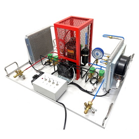
The refrigeration system using R404a as the refrigerant (such as showcases, cold storage, and refrigerated warehouses) has been arranged clearly on a tabletop pedestal. By operating the switch, it is possible to switch between cooling and heating, allowing for effective learning of the heat pump cycle. During cooling operation, the high-temperature, high-pressure refrigerant gas (superheated vapor) discharged from the compressor passes through the dryer, solenoid valve, and sight glass, where it is cooled and condensed (subcooled liquid) in the condenser. The low-temperature, low-pressure liquid refrigerant (saturated liquid) that passes through the capillary tube (expansion valve) via the sight glass enters the evaporator. In the evaporator, it undergoes heat exchange with air, providing latent heat of vaporization to the air, and the vaporized refrigerant (superheated vapor) returns to the compressor via the sight glass and solenoid valve.
Added to bookmarks
Bookmarks listBookmark has been removed
Bookmarks listYou can't add any more bookmarks
By registering as a member, you can increase the number of bookmarks you can save and organize them with labels.
Free membership registration
This is a tabletop experimental device for an open cooling tower (counterflow type) that cools the cooling water for building air conditioning and heating systems. Temperature-controlled warm water is sprayed from the top of the cooling tower and is cooled by air while passing through the packing material before returning to the water tank. The orifice at the intake measures the air volume, and the air sent by a variable speed fan is discharged from the bottom to the top of the cooling tower (counterflow). The measurement values from each sensor (temperature/humidity/flow/pressure) are digitally displayed on the control panel, and data can be collected and automatically calculated using the accompanying software on a PC (sold separately). The device comes with one standard cooling tower that is transparent, allowing for observation of the internal conditions. Additionally, a wide range of experiments can be conducted using four optional cooling towers available for separate purchase.
Added to bookmarks
Bookmarks listBookmark has been removed
Bookmarks listYou can't add any more bookmarks
By registering as a member, you can increase the number of bookmarks you can save and organize them with labels.
Free membership registration
This is a tabletop refrigeration system using refrigerant R134a. You will learn about the pressure-enthalpy diagram (p-h diagram) and derive subcooling and superheating, as well as the coefficient of performance (COP) from the enthalpy changes. The refrigeration circuit is equipped with high and low pressure gauges, pressure switches, a thermal expansion valve, a sight glass, and a dryer. The evaporator coil (evaporator) and condenser coil (condenser) submerged in the water tank accurately collect temperature changes, clearly demonstrating the heat pump. The water in the tank is circulated by a pump to maintain a steady state. High and low pressures and temperatures of each component are digitally displayed on the control panel's LCD screen, and various data can be displayed and collected on a PC (sold separately) using the included VDAS software. The compressor inlet temperature, thermal expansion valve inlet temperature, and low and high pressures are used to plot the p-h diagram, calculating cooling effect and heating effect (kJ/kg), compressor work (kJ/kg), cooling coefficient of performance (COPc), heating coefficient of performance (COPh), degree of subcooling (K), degree of superheating (K), and more.
Added to bookmarks
Bookmarks listBookmark has been removed
Bookmarks listYou can't add any more bookmarks
By registering as a member, you can increase the number of bookmarks you can save and organize them with labels.
Free membership registration
The air conditioning systems widely used in various industries and for improving living standards not only maintain comfort in daily life but also refer to the control of industrial process environments. The air conditioning system experimental device EC1501V demonstrates the cooling and dehumidification processes as well as the thermodynamic processes of refrigeration systems. The tabletop experimental device using R134a as the refrigerant is equipped with an evaporator in the center of the open duct, a fan at the right end, and a disk for flow adjustment. The transparent acrylic plate at the front allows for observation of the internal sensors and evaporator. The temperature of the refrigeration system, the temperature and humidity at the duct's inlet and outlet, and the high and low pressures are digitally displayed on the control panel's LCD display. Additionally, using the included VDAS software, various data can be displayed and collected on a PC (sold separately), and p-h diagrams and psychrometric charts can be drawn.
Added to bookmarks
Bookmarks listBookmark has been removed
Bookmarks listYou can't add any more bookmarks
By registering as a member, you can increase the number of bookmarks you can save and organize them with labels.
Free membership registration
The air conditioning systems widely used in various industries not only maintain the comfort of life but also refer to the control of industrial process environments, contributing to the improvement of living standards. The EC1550V is an apparatus equipped with an HVAC-R air conditioning system that demonstrates the thermodynamic processes of heating and humidifying, cooling, and refrigeration within ducts. The portable experimental device, using R134a as the refrigerant and equipped with movable casters, draws air from the intake grille on the left side of the duct. It passes through a manually operated damper, a variable speed axial fan, a primary heater, a steam humidifier, a heat exchanger (water-cooled), a water mist sprayer, a mist eliminator, and a secondary heater before being discharged from the exhaust grille on the right side of the duct. The temperature and humidity for each air conditioning process, the air velocity at one location within the duct, the refrigerant pressure (high and low), temperature, refrigerant flow rate, and compressor power consumption are displayed digitally. The chilled water tank, temperature-controlled by the refrigeration system, sends chilled water to the heat exchanger in the duct via a variable speed pump, and the inlet and outlet temperatures and flow rates of the heat exchanger are displayed digitally. The primary and secondary heaters, controlled by PID, can be compared in performance with different power inputs.
Added to bookmarks
Bookmarks listBookmark has been removed
Bookmarks listYou can't add any more bookmarks
By registering as a member, you can increase the number of bookmarks you can save and organize them with labels.
Free membership registration
This study examines the theory of heat transfer due to forced convection and various formulas related to forced convection in pipes. The apparatus consists of an electric fan, a heater-equipped copper pipe covered with insulation, a measuring display, and a control panel. The air drawn in by the fan and flow control valve enters the test copper pipe (with an inner diameter of 32mm) through an orifice. The air, heated by the heater, is discharged outside while passing through each measurement point. The control panel is equipped with four sets of manometers to measure the pressure loss of the fan, orifice flow rate, pressure loss in the copper pipe, and the differential pressure of the Pitot tube. Additionally, a temperature switch displays the temperatures from 14 thermocouples installed at various points on the copper pipe. The thermocouples are installed at seven locations on the outer surface of the copper pipe, three locations on the outer surface of the insulation pipe, and three locations on the inner surface of the insulation pipe. A Pitot tube with thermocouples is also included to measure the velocity distribution in the cross-section of the copper pipe. To avoid overheating, the heater is designed to stop when the air is not flowing as specified.
Added to bookmarks
Bookmarks listBookmark has been removed
Bookmarks listYou can't add any more bookmarks
By registering as a member, you can increase the number of bookmarks you can save and organize them with labels.
Free membership registration
This is a tabletop experimental device that demonstrates heat transfer (overall heat transfer) between adjacent fluids and verifies the effects of flow rate and temperature difference. The heat exchange experimental device TD360 offers optional (sold separately) experimental items including four types of double-pipe, plate, and multi-tube cylindrical heat exchangers, as well as a tank jacket (coil) type heat exchanger, with one of these being installed for experiments. The hot water system and cooling system are composed of a flow control valve and flow meter, with temperatures and flow rates displayed digitally. The hot water system consists of a PID-controlled tank with a heater, a pump, and a water level gauge, ensuring stable temperature and flow rate. The digital display shows the inlet and outlet temperatures of hot and cold water, the temperature of thermocouples integrated into the heat exchanger (sold separately), and the flow rates of hot and cold water, allowing experiments to be conducted without a PC (sold separately). The four types of heat exchangers (sold separately) have the same heat transfer area (0.02 m²) and wall thickness (1 mm), making it easy to compare each exchanger.
Added to bookmarks
Bookmarks listBookmark has been removed
Bookmarks listYou can't add any more bookmarks
By registering as a member, you can increase the number of bookmarks you can save and organize them with labels.
Free membership registration
This is a tabletop experimental device used for conducting calibration experiments on the characteristics (linearity), accuracy, and various thermometers commonly used for temperature measurement. The device consists of a heater (ON/OFF switch), a heater tank, an ice box, constant voltage and constant current output terminals, a voltage output display, a Wheatstone bridge circuit, and various resistance terminals, and it comes with eight types of thermometers. Additionally, experiments can be conducted smoothly using the included experimental manual. By using the optional (sold separately) data automatic collection system (VDAS-B), various data can be collected in real-time to a PC (sold separately) and the experimental results can be analyzed.
Added to bookmarks
Bookmarks listBookmark has been removed
Bookmarks listYou can't add any more bookmarks
By registering as a member, you can increase the number of bookmarks you can save and organize them with labels.
Free membership registration
This is a tabletop device that demonstrates the relationship between pressure and volume of an ideal gas at a constant temperature (Boyle's Law). It consists of a test cylinder and a reservoir tank, a mechanical pressure gauge, a thermocouple with a digital display, and a digital level gauge, along with a manual pressure pump and a vacuum pump for pressure variation. The experiment is conducted using dry air from the atmosphere while keeping the air temperature constant. The pressure in the reservoir tank (on the left) is increased or decreased using the manual pump, which moves the liquid piston (oil) in the test cylinder (on the right). Boyle's Law is verified through the changes in air pressure, temperature, and volume contained within the test cylinder. The device comes with pressure and temperature sensors, as well as level gauge connection cables, and can utilize an optional (sold separately) data acquisition system (VDAS-B) to collect and analyze various data in real-time on a PC (sold separately).
Added to bookmarks
Bookmarks listBookmark has been removed
Bookmarks listYou can't add any more bookmarks
By registering as a member, you can increase the number of bookmarks you can save and organize them with labels.
Free membership registration
This is a tabletop experimental device that demonstrates Charles's (Gay-Lussac's) law, which shows that the volume of an ideal gas is proportional to its absolute temperature when the pressure is constant. A pressure sensor and three thermocouples are installed in a heated adiabatic container, and the measurement data is displayed digitally. One thermocouple measures the surface temperature of the heater for control, while the other two measure the air temperature inside the container. The digital display shows the pressure inside the container, the air temperatures at two locations, and their average value. It measures the relationship between the pressure and temperature of an ideal gas (air) to demonstrate Charles's law. The device can also operate in reverse. By heating with the valve open and releasing the air inside the container before closing the valve, it records the pressure and temperature drop as the container cools down. This allows for results to be obtained under various starting points and ambient conditions. The optional VDAS automatic recording function is useful for slow natural cooling experiments. By using the optional (sold separately) data acquisition system (VDAS-B), various data can be collected and analyzed in real-time on a PC (sold separately).
Added to bookmarks
Bookmarks listBookmark has been removed
Bookmarks listYou can't add any more bookmarks
By registering as a member, you can increase the number of bookmarks you can save and organize them with labels.
Free membership registration
This is a tabletop experimental device for comparing and verifying the thermal conductivity and heat transfer rates of various metals. The heat transfer experimental device consists of a heater power supply and a measurement data display unit, and experiments are conducted by attaching one of the optional items TD1002a to d (sold separately). The heat transfer experimental device (TD1002) supplies variable current to the heater of the optional device, and a safety switch prevents the heater from overheating. In the spare space on the right side of the device, an optional (sold separately) data automatic collection system (VDAS-F) can be installed, allowing for real-time collection and analysis of various data to a PC (sold separately) using the data automatic collection system.
Added to bookmarks
Bookmarks listBookmark has been removed
Bookmarks listYou can't add any more bookmarks
By registering as a member, you can increase the number of bookmarks you can save and organize them with labels.
Free membership registration
This is a tabletop experimental device that conducts experiments on natural convection, forced convection, and heat transfer using heater modules with different surface shapes. The device consists of a duct measuring 128mm x 75mm, a removable fan, and three types of heater modules. Three thermocouples measure the temperature at the inlet and outlet of the duct, as well as the surface temperature of the heater modules. Additionally, a manual thermocouple is included to measure the surface temperature at six locations along the module from the side of the duct. The measured temperatures and wind speeds are displayed in real-time on a digital display. Furthermore, by using an optional (sold separately) data acquisition system (VDAS-B), various data can be collected and analyzed in real-time on a PC (sold separately).
Added to bookmarks
Bookmarks listBookmark has been removed
Bookmarks listYou can't add any more bookmarks
By registering as a member, you can increase the number of bookmarks you can save and organize them with labels.
Free membership registration
This is a tabletop experimental device designed to clarify the relationship between saturated vapor pressure and temperature, and to compare theoretical values. The device, composed of a stainless steel heating container (boiler) and a control unit, is compactly designed for tabletop experiments and conducts tests on the variations of saturated vapor pressure with temperature, as well as the verification of the Antoine equation. When water is added to the boiler and heated, the temperature and pressure of the water rise. Sensors read the temperature and pressure, displaying them digitally, while a mechanical Bourdon tube pressure gauge also shows the pressure inside the boiler. Additionally, a front observation window allows for the observation of the boiling process inside the boiler and the checking of the water level. For safety, the heating element is equipped with a thermostat to limit the heater temperature and a relief valve to limit the boiler pressure. In the space on the right side of the device, an optional (sold separately) data automatic collection system (VDAS-F) can be installed. By using the data automatic collection system, various data can be collected in real-time to a PC (sold separately), allowing for the analysis of experimental results.
Added to bookmarks
Bookmarks listBookmark has been removed
Bookmarks listYou can't add any more bookmarks
By registering as a member, you can increase the number of bookmarks you can save and organize them with labels.
Free membership registration
This is a system commonly used in heating and cooling air conditioning equipment for buildings and houses, as well as radiators. It is a tabletop experimental device where heated hot water circulates through copper pipes in a heat exchanger and exchanges heat with the air flowing through a wind tunnel. The device comes with a 32-tube heat exchanger, and as an option (sold separately), 16-tube and 16-tube fin-type heat exchangers are available, allowing experiments to be conducted with either type of heat exchanger installed. The hot water system consists of a tank with a PID-controlled heater, a pump, and a water level gauge, and it digitally displays the inlet and outlet temperatures and flow rate of the hot water. The air supply duct system is made up of an orifice and pressure holes for flow measurement, an electric fan, and a slide valve, and it digitally displays the temperatures at the duct inlet and the inlet and outlet of the heat exchanger, as well as the differential pressure across the orifice. In the empty space on the right side of the device, an optional (sold separately) data automatic collection system (VDAS-F) can be installed. By using the data automatic collection system, various data can be collected in real-time to a PC (sold separately), allowing for the analysis of experimental results.
Added to bookmarks
Bookmarks listBookmark has been removed
Bookmarks listYou can't add any more bookmarks
By registering as a member, you can increase the number of bookmarks you can save and organize them with labels.
Free membership registration
This is a tabletop device that conducts performance experiments on thermoelectric power generation using the Peltier effect, which creates a temperature difference from the voltage between dissimilar metals, and the Seebeck effect, which generates voltage from a temperature difference. In the Seebeck effect experiment, the voltage generated from the temperature difference between the cooling surface and the hot surface of the device is measured using cold water from an external source and variable electric heater output. In the Peltier effect experiment, the surface temperature difference of the device is measured by adjusting the electric heater, water storage tank, and water supply pump. By accurately measuring the flow of water, the amount of heat transfer can be calculated, allowing for the evaluation of performance based on temperature gradient and power, as well as the analysis of the coefficient of performance (COP) and energy balance in each mode. The device panel features a schematic diagram and digitally displays heater output (W), cooling water inlet temperature (°C), device surface temperatures (top and bottom), voltage, current, and power. By using the optional (sold separately) data automatic collection system (VDAS-B), various data can be collected in real-time to a PC (sold separately), enabling the analysis of experimental results.
Added to bookmarks
Bookmarks listBookmark has been removed
Bookmarks listYou can't add any more bookmarks
By registering as a member, you can increase the number of bookmarks you can save and organize them with labels.
Free membership registration
This device experiments on how heat is transmitted by large changes in pressure, clarifying the differences between radiation and natural convection. It consists of a steel pressure vessel (cylindrical), a control device, a vacuum pump, and a regulator for compressed air. A small heater is suspended in the center of the pressure vessel, and thermocouples for temperature measurement are attached to the heater surface and the vessel wall. The temperatures of the heater and vessel, as well as the pressure, are displayed digitally. Additionally, the heater surface and the inside of the vessel are blackened to act as ideal thermal radiators. In the experiment, compressed air can be filled up to a maximum of 125 kPa (gauge pressure), and a vacuum of approximately -100 kPa (gauge pressure) can be achieved. Creating a vacuum state reduces heat loss due to convection, allowing for more accurate measurements of heat transfer. The emissivity of the surface is measured, demonstrating Stefan-Boltzmann's law, and understanding dimensionless characteristics using the Nusselt number, Grashof number, Prandtl number, and Knudsen number. By using the accompanying data acquisition system (VDAS), various data can be collected and analyzed in real-time on a PC (sold separately).
Added to bookmarks
Bookmarks listBookmark has been removed
Bookmarks listYou can't add any more bookmarks
By registering as a member, you can increase the number of bookmarks you can save and organize them with labels.
Free membership registration
You will learn the basic principles of thermodynamics, heat energy conversion, and power measurement using a boiler and steam engine. Water pumped from the storage tank by the feedwater pump is heated in the boiler and turns into steam, which drives a two-cylinder steam engine. The steam that exits the engine passes through a water-cooled condenser and enters a drainage tank or steam measurement container. A manually operated load device connected to the steam engine measures the engine's rotational speed, torque, and output, while thermocouples measure the temperature inside the boiler, the temperature of the throttling calorimeter, and the inlet and outlet temperatures of the cooling water for the condenser, displaying them digitally. The throttling calorimeter measures the dryness of the steam based on the heat quantity. Two analog gauges display the inlet pressure of the boiler and engine, and an electric meter shows the heater power. The analysis of the Rankine cycle and verification of steam plant performance, including the Mollier diagram, clarify the relationship between pressure and temperature through boiler experiments with saturated steam. For safety, if the water level in the boiler drops and the heater overheats, the heater will automatically stop, and a lamp will light up. Additionally, the safety valve of the boiler limits the pressure.
Added to bookmarks
Bookmarks listBookmark has been removed
Bookmarks listYou can't add any more bookmarks
By registering as a member, you can increase the number of bookmarks you can save and organize them with labels.
Free membership registration
The device consists of a main unit made up of a glass container, a heating heater, a water circulation pump, a heating wire test specimen, and a water-cooled cylinder test specimen (with copper oxide surface and gold-plated surface), as well as a control unit composed of a wire temperature adjustment volume and a digital display (showing water temperature, water flow rate, voltage, and current). In the boiling heat transfer experiment, the heater wire (resistor) placed inside the glass container is heated, and the transition from subcooled boiling to nucleate boiling and unstable film boiling is observed, drawing a boiling curve based on heat flux and degree of superheat. This metal wire generates high heat exceeding 100°C. In the condensation heat transfer experiment, the heat transfer due to the condensation phenomenon that occurs when steam contacts the surface of the water-cooled cylinder test specimen placed inside the glass container is measured. The heat transfer rate is derived from the temperature changes at the inlet and outlet of the water flowing through the cylinder test specimen and the flow rate. To clarify the effect of surface finishing on heat transfer, there are two types of finishes on the cylinder test specimen: gold plating and oxide film finishing, which reveal the differences between filmwise and dropwise condensation. By using the optional data automatic collection system VDAS-B (sold separately), various data can be collected and analyzed in real-time on a PC (sold separately).
Added to bookmarks
Bookmarks listBookmark has been removed
Bookmarks listYou can't add any more bookmarks
By registering as a member, you can increase the number of bookmarks you can save and organize them with labels.
Free membership registration
The amount of heat transfer due to forced convection is measured, and the cooling rate of a heated object in the airflow is observed. The air inhaled from the bell mouth is released into the atmosphere after passing through the experimental area (pin-shaped module), diffusion body, constant-speed fan and flow control valve, and silencer. A thermocouple is used to measure the temperature of the incoming air at the wind tunnel entrance, and there are two static pressure ports and a pitot tube mounting point before and after the pin-shaped module. The pitot tube can be mounted either in front or behind to measure the velocity distribution in the cross-sectional direction. In the experimental area, pins are arranged perpendicular to the wind direction, and one of them can be removed and replaced with a pin-type heater. The pin-type heater is equipped with a thermocouple, allowing for the measurement of heat transfer based on the time it takes for the temperature to decrease and the wind speed. The control unit has thermocouple connection ports (two), pressure connection ports (differential pressure, two), and a heater power switch, and it digitally displays the temperatures from the two locations, the differential pressure before and after the pin-shaped module, and the differential pressure between the total pressure and static pressure of the pitot tube. By using the optional (sold separately) data automatic collection system VDAS-B, various data can be collected and analyzed in real-time on a PC (sold separately).
Added to bookmarks
Bookmarks listBookmark has been removed
Bookmarks listYou can't add any more bookmarks
By registering as a member, you can increase the number of bookmarks you can save and organize them with labels.
Free membership registration
This is a very suitable teaching material for demonstrating thermal engineering, as it is a heat engine close to the Carnot cycle that heats and cools the gas inside the cylinder, converting the thermal energy from its volume changes into work. The power generated by the engine is converted into electrical energy (W) using a motor generator or into mechanical energy (Nm) using a torque meter. Additionally, experiments on a refrigeration cycle can be conducted using an external power source (sold separately). The included interface and software can display in real-time the cylinder pressure (kPa), rotational speed (rpm), cylinder volume (cm³), crank angle, and temperature data for both the heating and cooling sides of the displacer on a PC (sold separately), as well as plot P-V diagrams and estimate the efficiency of the Stirling engine.
Added to bookmarks
Bookmarks listBookmark has been removed
Bookmarks listYou can't add any more bookmarks
By registering as a member, you can increase the number of bookmarks you can save and organize them with labels.
Free membership registration
It consists of a circulating water tank and pump, flow control valve and flow sensor, propeller turbine with guide vanes, generator, and electrical load device. Five propeller turbines of different shapes are included to investigate the efficiency of various propellers and analyze the performance of the power generation system. Additionally, please try creating your own turbine using a 3D printer or similar equipment for experimentation. The turbine mounting section (drain outlet) is designed with transparent resin to allow for internal observation.
Added to bookmarks
Bookmarks listBookmark has been removed
Bookmarks listYou can't add any more bookmarks
By registering as a member, you can increase the number of bookmarks you can save and organize them with labels.
Free membership registration
It consists of an electric heating boiler, a single-stage axial flow impulse turbine, a variable load device (generator), a condenser with a cooling fan, a water tank, and a circulation pump. The water sent to the boiler by the circulation pump is heated by the electric heater to become high-temperature, high-pressure steam, which is injected from four nozzles to rotate the turbine and drive the generator. The used steam is cooled in the condenser with a cooling fan and returned to the water tank. The boiler is temperature-controlled by a PID-controlled electric heater and is equipped with a pressure relief valve and thermal trip for safety.
Added to bookmarks
Bookmarks listBookmark has been removed
Bookmarks listYou can't add any more bookmarks
By registering as a member, you can increase the number of bookmarks you can save and organize them with labels.
Free membership registration
This is a device that uses R1234yf, a refrigerant developed as a substitute for HFC-134a. Compared to HFC-134a, it has a lower ozone depletion potential and global warming potential, making it an environmentally friendly refrigerant. The refrigeration system using R1234yf (refrigerant for car air conditioning and vending machines) is clearly arranged on a tabletop base. The EC2002 has an added heating and cooling switch compared to the EC2001, allowing for effective learning of the heat pump cycle. The high-temperature, high-pressure refrigerant gas (superheated vapor) discharged from the compressor passes through the dryer, solenoid valve, and sight glass, where it is cooled and condensed (subcooled liquid) in the condenser. The low-temperature, low-pressure liquid refrigerant (saturated liquid) that passes through the capillary tube (expansion valve) via the sight glass enters the evaporator, where it undergoes heat exchange with air, providing latent heat of vaporization to the air. The vaporized refrigerant (superheated vapor) then returns to the compressor via the sight glass and solenoid valve. By measuring the pressure and temperature at each part, a P-h diagram (pressure-enthalpy diagram) is created, and the coefficient of performance (COP) of this device is calculated from the inlet pressure and temperature of the compressor and the compressor efficiency.
Added to bookmarks
Bookmarks listBookmark has been removed
Bookmarks listYou can't add any more bookmarks
By registering as a member, you can increase the number of bookmarks you can save and organize them with labels.
Free membership registration
This is a device that uses R1234yf, a refrigerant developed as a substitute for HFC-134a. Compared to HFC-134a, it has a lower ozone depletion potential and global warming potential, making it an environmentally friendly refrigerant. The refrigeration system using R1234yf (refrigerant for car air conditioners and vending machines) is clearly arranged on a tabletop base. The high-temperature, high-pressure refrigerant gas (superheated vapor) discharged from the compressor passes through the dryer, solenoid valve, and sight glass, where it is cooled and condensed into a liquid (subcooled liquid) in the condenser. The low-temperature, low-pressure liquid refrigerant (saturated liquid) that passes through the capillary tube (expansion valve) via the sight glass enters the evaporator, where it undergoes heat exchange with air, providing latent heat of vaporization to the air. The vaporized refrigerant (superheated vapor) then returns to the compressor through the sight glass and solenoid valve. A P-h diagram (pressure-enthalpy diagram) is created from the measured pressures and temperatures of each component, and the coefficient of performance (COP) of this device is calculated from the inlet pressure and temperature of the compressor and the compressor efficiency.
Added to bookmarks
Bookmarks listBookmark has been removed
Bookmarks listYou can't add any more bookmarks
By registering as a member, you can increase the number of bookmarks you can save and organize them with labels.
Free membership registration
The tabletop tensile testing machine, specially designed for educational purposes, performs tensile and compression tests by applying loads of up to 20 kN using a rotary handle hydraulic pump. The test load is displayed in kilonewtons (kN) on a large, easy-to-read gauge and is recorded (with a needle indicator) for the maximum load. The elongation of the test specimen is measured with a digital dial gauge with an accuracy of 0.001 mm. The test specimens for tensile testing (with a diameter of 5.0 mm) can be easily attached to the device using a screw type (M10), and four types of specimens made from different materials are available (iron, aluminum, brass, copper). A PC connection kit (SM1250) is included, allowing for the observation and data collection of load (N) and elongation values (mm) on a computer (sold separately).
Added to bookmarks
Bookmarks listBookmark has been removed
Bookmarks listYou can't add any more bookmarks
By registering as a member, you can increase the number of bookmarks you can save and organize them with labels.
Free membership registration
This is a training device that uses the next-generation refrigerant R32, which balances environmental load reduction and energy efficiency improvement. The refrigeration system is clearly arranged on a tabletop base, allowing for effective learning of the heat pump cycle. The operation can be switched between cooling and heating with a switch. During cooling operation, the high-temperature, high-pressure refrigerant gas (superheated vapor) discharged from the compressor passes through the sight glass and is cooled and condensed (subcooled liquid) in the condenser. The low-temperature, low-pressure liquid refrigerant (saturated liquid) that passes through the capillary tube (expansion valve) via the sight glass enters the evaporator. In the evaporator, it undergoes heat exchange with air, providing latent heat of vaporization to the air, and the vaporized refrigerant (superheated vapor) returns to the compressor via the sight glass. By measuring the pressure and temperature at each part, a P-h diagram (pressure-enthalpy diagram) is created, and the coefficient of performance (COP) of this device is calculated from the inlet pressure and temperature of the compressor and the compressor efficiency. By using the optional Kits Windows (EC2000 version) software, it becomes easier to calculate the theoretical cycle, draw the P-h diagram (Mollier diagram), and calculate the coefficient of performance (COP), allowing for comparisons with different refrigerants.
Added to bookmarks
Bookmarks listBookmark has been removed
Bookmarks listYou can't add any more bookmarks
By registering as a member, you can increase the number of bookmarks you can save and organize them with labels.
Free membership registration