We have compiled a list of manufacturers, distributors, product information, reference prices, and rankings for soft.
ipros is IPROS GMS ・ IPROS One of the largest technical database sites in Japan that collects information on.

soft(3D CAD) - List of Manufacturers, Suppliers, Companies and Products | IPROS GMS

Last Updated: Aggregation Period:Sep 16, 2026~Oct 13, 2026
This ranking is based on the number of page views on our site.

soft Product List

211~240 item / All 747 items

Displayed results

OPTICAM Classic: CAD/CAM Software

Simple and productive. Advanced flexibility and diversity for various machining processes!

"OPTICAM Classic" is one of the leading CAD/CAM systems with over 30 years of practical experience and more than 40,000 sheets of achievements. It is an innovative, CAD-independent system that caters to all genres from micro-machining to large-scale machining. The milling and wire modules enable automatic NC program generation through automatic feature recognition and automatic process assignment. 【Features】 ■ Fully automated NC program generation using feature recognition ■ Extensive machining capabilities ■ Comprehensive technology database ■ 3D simulation including interference checks *For more details, please refer to the PDF document or feel free to contact us.

  • Other CAD related software
  • Other CAM related software
  • Other CAD
  • soft

Added to bookmarks

Bookmarks list

Bookmark has been removed

Bookmarks list

You can't add any more bookmarks

By registering as a member, you can increase the number of bookmarks you can save and organize them with labels.

Free membership registration

Example: Silent Design of Electromagnetic Field Reactor

By integrating various software such as CAD, magnetic field analysis, and acoustic analysis, a wide range of optimization can be achieved!

This example introduces the integration of three software programs to reduce noise without compromising the electrical performance of a reactor. First, the general-purpose parameter optimization software "AMDESS" rewrites the VB script file of the 3D CAD software "SolidWorks" with trial dimensions and modifies the model dimensions. Next, the electromagnetic field analysis software "JMAG" communicates with "SolidWorks" to import the CAD model, performs meshing and analysis, and "AMDESS" extracts responses from the analysis results of "JMAG." As a result, starting from 30 samples using Latin hypercube sampling, a 31% reduction in sound pressure was achieved through six updates of the response surface. 【Optimization Conditions】 ■ Design Variables: Core dimensions D1 to D4 ■ Objective Function: Minimization of reactor sound pressure ■ Constraint Functions: Inductance greater than or equal to the initial value, core volume less than or equal to the initial value ■ Approximation Model: RBF *For more details, please refer to the PDF document or feel free to contact us.

  • Other analyses
  • Contract Analysis
  • simulator
  • soft

Added to bookmarks

Bookmarks list

Bookmark has been removed

Bookmarks list

You can't add any more bookmarks

By registering as a member, you can increase the number of bookmarks you can save and organize them with labels.

Free membership registration

[START Function Introduction] Touch Panel Module 3D Implementation Design Process Design

Customize your own rules for bulk placement! By inputting parameters in Excel, you can automatically create 3D structures and shapes.

This document introduces the touch panel module 3D implementation design/process design of the CAD/CAM integration programming tool 'START'. It enables integrated workflow and centralized management from circuit design/board design/3D structuring/analysis models/manufacturing design/editing/inspection to the output of drawings for factories and customer mechanism verification drawings. Additionally, practical examples of panel design are also included. We encourage you to read it. [Contents (partial)] ■ FPD design/process design tools ■ Direct interface to suitable 3D analysis model Q3D ■ Three-dimensional integration connection checks of various separately designed data ■ Touch panel design/process design tools ■ User customization examples *For more details, please refer to the PDF document or feel free to contact us.

  • 2D CAD Electrical
  • soft

Added to bookmarks

Bookmarks list

Bookmark has been removed

Bookmarks list

You can't add any more bookmarks

By registering as a member, you can increase the number of bookmarks you can save and organize them with labels.

Free membership registration

"Fusion360" User Case Collection

Case studies of 8 companies that have implemented 3D CAD/CAM "Fusion360"!

○Contents○ ■ Kabuku Inc. Customizing Honda's ultra-compact electric vehicle Aiming for the forefront of manufacturing with 3D printers and a unique digital manufacturing platform ■ Jinan Inc. What is a flexible and speedy design process for truly innovative products in a short period of time? ■ Takara Tomy Co., Ltd. Development of educational toys that combine safety and exterior design, made possible by Fusion360's CAM features, bringing cutting and processing closer to home ■ Xenoma Inc. Taking wearables a step further with Fusion360 ■ Noguchi Automobile Co., Ltd. Fully utilizing the long-desired 3D CAD for special vehicle design in a short period of time ■ Photosys Inc. A smart lock designed entirely with Fusion360 that realizes safety management for the next generation of offices and residences ■ Oaks Co., Ltd. Fusion360 is utilized to realize the commitment to innovative kitchen tools that seemed non-existent ■ GENKEI LLC With "everything you need" for the product development process, manufacturing is entering a new phase centered around Fusion360

  • 3D CAD
  • 3D CAM
  • Stress Analysis
  • soft

Added to bookmarks

Bookmarks list

Bookmark has been removed

Bookmarks list

You can't add any more bookmarks

By registering as a member, you can increase the number of bookmarks you can save and organize them with labels.

Free membership registration

3D modeling tool series "Geomagic Freeform"

It is a new sensation modeling tool that allows you to "touch" and design models within the screen. It is equipped with comprehensive features for design and manufacturing. *Demo available.

"Geomagic Freeform/Freeform Plus" is a new sensation virtual clay modeling tool that allows you to create 3D models by "touching" virtual clay. Unlike traditional CAD, which is constrained by numerical values, you can create complex and organic shapes and designs by adding volume, pulling, and applying fine embossing. [Features] ■ "Touch" the design on the screen Modeling is done using a dedicated device instead of moving the mouse cursor on a flat surface. When you hold the stylus and operate it, the user’s hand receives feedback as if they are actually touching the model. ■ Capable of expressing fine designs You can create complex and organic designs that cannot be expressed with traditional CAD. Anyone can intuitively digitize new ideas immediately. ■ Streamlining product design and manufacturing workflows Freeform Plus is equipped with features for design and manufacturing, such as detecting undercuts for mold design and defining parting lines. *For more details, please request a catalog or view the PDF data from the download button below.

  • Other CAD
  • Modeler
  • 3D CAD
  • soft

Added to bookmarks

Bookmarks list

Bookmark has been removed

Bookmarks list

You can't add any more bookmarks

By registering as a member, you can increase the number of bookmarks you can save and organize them with labels.

Free membership registration

Graphic software and file formats compatible with our laser processing machines.

Directly import from graphic software and output with printing functionality!

Trotec's laser processing machines can perform laser processing via printer drivers from graphic software print settings or through direct import. When using the JobControl software and Ruby for the Speedy series (flatbed laser), it is possible to directly import from graphic software or output using the print function. Additionally, you can use the SpeedMark marking laser software for galvo lasers to create defined serial numbers or codes. 【Supported File Formats】 ■ Vector: *.cdr, *.ai, *.svg ■ Bitmap/Raster: *.cpt, *.ps, *.bmp, *.jpg, *.tiff, *.gif, *.png ■ Composite: *.pdf, *.eps ■ CAD/3D Design: Please contact us for details. *For more information, please refer to the related links or feel free to contact us.

Added to bookmarks

Bookmarks list

Bookmark has been removed

Bookmarks list

You can't add any more bookmarks

By registering as a member, you can increase the number of bookmarks you can save and organize them with labels.

Free membership registration

Setting bulk hole attributes to 3D models in 【iCAD×meviy】.

No need for 2D disassembly! By linking the 3D model and hole attribute information of iCAD to meviy, it is possible to estimate machine parts in just one minute.

Are you creating 2D drawings for processing instructions even though you are designing in 3D CAD? By using the 3D CAD specialized for mechanical design, "COLMINA Design and Manufacturing Support iCAD SX (hereafter referred to as iCAD)," along with the online mechanical parts procurement service "meviy," you can easily arrange for parts. When you upload a 3D model created in iCAD, you can automatically link and reflect hole attribute information to meviy, allowing you to obtain quotes for mechanical parts in just one minute. This significantly reduces the time-consuming tasks of creating 2D drawings and obtaining quotes, improving both design quality and work efficiency, and greatly enhancing the customer’s parts procurement process. → For more details, please refer to the link at the end of the text. Additionally, iCAD has developed a function that allows you to set hole attributes in bulk, which can be lost when going through intermediate files, thanks to its shape recognition technology specialized for mechanical design. It can derive candidates for hole attributes from the shape of the 3D model, making it easy to set hole attributes. For actual operation methods, please refer to the related videos. Collaboration videos of iCAD × Meviy are currently available on the official Misumi YouTube channel.

Added to bookmarks

Bookmarks list

Bookmark has been removed

Bookmarks list

You can't add any more bookmarks

By registering as a member, you can increase the number of bookmarks you can save and organize them with labels.

Free membership registration

5-axis CAD/CAM software [hyperMILL]

A 5-axis CAD/CAM system that generates excellent 5-axis tool paths with simple operations and has a quick startup from practical implementation.

hyperMILL, which offers innovative CAM technology, features a simple and user-friendly interface, a highly reliable interference detection algorithm, and intelligent interference avoidance functions, allowing for quick programming of 2D to 3D, indexing/simultaneous 5-axis, and complex machining. With hyperMILL's high-speed machining "MAXX Machining," it is possible to improve surface quality and reduce costs through finishing tool paths that utilize barrel tools in addition to high-speed rough machining. Furthermore, hyperMILL's new simulation system "VIRTUAL Machining" enables NC code-based simulations that differ from traditional methods. Additionally, we provide forward-looking solutions such as "AUTOMATION Center" for automating programming and "Probing" for programming on-machine measurement.

Added to bookmarks

Bookmarks list

Bookmark has been removed

Bookmarks list

You can't add any more bookmarks

By registering as a member, you can increase the number of bookmarks you can save and organize them with labels.

Free membership registration

Injection Molding CAE Software

This is the world's first 3D injection molding CAE system developed and sold by Toray. Plastic parts designed with 3D CAD can be tested without actual prototyping.

3D TIMON is an injection molding system that has pioneered three-dimensional warpage analysis of injection molded products and has quickly realized the application of warpage analysis technology in design, prototyping, and production environments. Furthermore, we provide solutions that leverage three-dimensional resin flow analysis, such as insert molding warpage analysis and birefringence prediction for optical components.

  • simulator
  • soft

Added to bookmarks

Bookmarks list

Bookmark has been removed

Bookmarks list

You can't add any more bookmarks

By registering as a member, you can increase the number of bookmarks you can save and organize them with labels.

Free membership registration

High-End Mesh Morphing DEP MeshWorks

Support with a variety of features! Streamlining advanced shape modifications at the CAE level and reducing costs.

"DEP MeshWorks" is a high-end mesh morphing software developed based on the technique of "morphing," which utilizes existing mesh models to change only the node and element shapes without altering the CAD geometry. This minimizes the need to revert to CAD, allowing for significant reductions in man-hours during the CAE model preparation process. Additionally, it is equipped with a wide range of features that support mesh-based modeling, such as feature insertion into mesh data, stitching functions, and shape-wrapping mesh capabilities. 【Features】 ■ Abundant morphing functions (freeform, control block, stretch, pattern, fillet modification) ■ Diverse advanced features that support shape changes based on mesh ■ Multiple morphing sets can be configured (parametric FEM/CFD) ■ Integration with optimization software ■ Widely adopted by many automotive, parts, and aircraft manufacturers *For more details, please refer to the PDF document or feel free to contact us.

  • Company:IDAJ
  • Price:Other
  • Thermo-fluid analysis
  • Contract Analysis
  • Other analyses
  • soft

Added to bookmarks

Bookmarks list

Bookmark has been removed

Bookmarks list

You can't add any more bookmarks

By registering as a member, you can increase the number of bookmarks you can save and organize them with labels.

Free membership registration

PTC Creo ジェネレーティブ・デザイン・ソリューション

AIベースの最適化エンジンによる高精度・高速な形状生成を実現。設計リードタイムの短縮に貢献

『PTC Creo Generative Designソリューション』は、AIベースの最適化エンジンにより、 高精度かつ高速に最適化された形状を生成できる設計支援ソリューションです。 トポロジー最適化(GTO)と数値最適化(BMX)を組み合わせることで、 設計者の意図を保ちながら、軽量化・高剛性化・設計品質向上が図れます。 3DCAD「Creo」環境に統合された直感的な操作性と即時再計算機能により、 生成された結果をそのままCADモデルに変換できるなど、高い実用性も特長です。 【特長】 ■AIベースの最適化エンジンによる高精度かつ高速な形状生成 ■設計意図を反映した最適設計が可能。設計リードタイムの短縮にも貢献 ■CADモデルへの変換が容易でそのまま設計に活用可能 ■質量約23%削減、材料使用量約10~15%削減に貢献したユーザー事例あり ★2025年11月27日にオンライン(事前登録制)にて、  Webセミナー「リアルDX改革者が語る4つの重大要素とは?」を開催します。  参加をご希望の方は、下記リンク先よりお申込みください。

  • 3D CAD
  • soft

Added to bookmarks

Bookmarks list

Bookmark has been removed

Bookmarks list

You can't add any more bookmarks

By registering as a member, you can increase the number of bookmarks you can save and organize them with labels.

Free membership registration

Company-wide utilization of 3D design data, the key to DX in the manufacturing industry!

Connecting "design" and "manufacturing site" with the power of 3D for efficiency! Utilizing design 3D data non-stop from production to manufacturing to sales to service!

The strength of Japan's manufacturing industry lies in its "on-site capabilities," but feedback to design is often based on "2D drawings." Even when 3D design is used, information is frequently conveyed to the site in the form of "2D drawings." Since "2D drawings" require reading skills, there is a tendency for incorrect information to be communicated, especially for those who are not familiar with them. As the transfer of technology becomes more challenging, relying primarily on "2D drawings" for information sharing increasingly leads to inefficiencies. The ultra-lightweight 3D format 'XVL,' which utilizes 3D design data, transforms 3D data into a form that can be utilized on-site, aiming to enhance manufacturing efficiency through digital capabilities and promote DX that leverages the "on-site capabilities" that are a strength of Japan's manufacturing industry. 【Abundant Solutions】 ■ Manufacturing Department Process design and work instruction creation solutions ■ Sales and Marketing Department Promotion solutions ■ Service Department Parts catalog solutions Various manual illustration solutions *For more details, please refer to the PDF document or feel free to contact us.

Added to bookmarks

Bookmarks list

Bookmark has been removed

Bookmarks list

You can't add any more bookmarks

By registering as a member, you can increase the number of bookmarks you can save and organize them with labels.

Free membership registration

CAD software APEXFiz PGM developed by a pattern maker.

"APEXFiz PGM" is a CAD software that supports the entire process of manufacturing from pattern design to size development and cutting, anytime and anywhere.

The apparel design CAD, SDS-ONE APEX series, is now available as a highly anticipated subscription service. APEXFiz PGM (Apex Fiz PGM) features independent software for pattern making, grading, and marking, supporting the entire manufacturing process from pattern design to size development and cutting anytime, anywhere. ◆ Product Lineup APEXFiz PGM offers four product variations, ranging from entry-level models to full-spec software, allowing customers to choose the software that meets their needs. ◆ Options We provide various options, including conversions for general formats, AutoMarking Premium, and 3D options. Please feel free to contact us with any questions about APEXFiz PGM or to request a presentation.

  • Image Processing Software
  • soft

Added to bookmarks

Bookmarks list

Bookmark has been removed

Bookmarks list

You can't add any more bookmarks

By registering as a member, you can increase the number of bookmarks you can save and organize them with labels.

Free membership registration

[Case Study of 3D CAD Software for Mechanical Design] Sun Industry Co., Ltd.

Free presentation of case studies: Create high value-added manufacturing!

We would like to introduce a case study of the implementation of "iCAD SX" at Sun Kogyo Co., Ltd., a manufacturer of plant equipment and facilities. In pursuit of higher value-added manufacturing, we focused on the possibilities of 3D design and adopted this product. By visualizing the shapes of plant equipment and facilities in three dimensions, which were difficult to grasp in 2D drawings, we enable efficient and waste-free manufacturing. 【Case Overview (Partial)】 ■Challenges - Interference between parts and equipment - Issues that were difficult to identify in 2D drawings became apparent during manufacturing or installation, necessitating rework - The imagination required to bridge the gap between 2D drawings and 3D objects is strongly developed through experience, making it challenging for less experienced young engineers *For more details, please refer to the PDF document or feel free to contact us.

Added to bookmarks

Bookmarks list

Bookmark has been removed

Bookmarks list

You can't add any more bookmarks

By registering as a member, you can increase the number of bookmarks you can save and organize them with labels.

Free membership registration

For reverse engineering, Elysium 3DxSUITE.

Reverse engineering feature boasting a high automation rate 【1-month free trial available】

The greatest feature of Elysium 3DxSUITE's reverse engineering function is its high level of automation. It can automatically identify areas such as fillets, base surfaces, planes, and cylinders from polygon data, even with complex shapes, allowing for the easy creation of high-quality CAD data. Additionally, it includes a function to convert point cloud data measured in three dimensions with a 3D scanner into polygon data, as well as features to verify and correct local missing or duplicate areas in the polygon data. The workflow from measurement to CAD modeling can be achieved with simple operations by just pressing an icon.

  • simulator
  • soft

Added to bookmarks

Bookmarks list

Bookmark has been removed

Bookmarks list

You can't add any more bookmarks

By registering as a member, you can increase the number of bookmarks you can save and organize them with labels.

Free membership registration

EZ-CAM

It is a user-friendly CAD/CAM software that thoroughly reflects the voices from the field.

With over 20 years of accumulated experience in G-code programming and know-how related to CNC, we can accommodate all types of machine tools. Our powerful shape creation tools are easy to learn and use. With multiple input and output options, including DXF and IGES, you can quickly import data from existing CAD systems.

  • 2D CAM
  • 3D CAM
  • Other CAM related software
  • soft

Added to bookmarks

Bookmarks list

Bookmark has been removed

Bookmarks list

You can't add any more bookmarks

By registering as a member, you can increase the number of bookmarks you can save and organize them with labels.

Free membership registration

CADSUPER integration for SOLIDWORKS

Batch processing from SOLIDWORKS 3D assembly data to assembly drawings/part drawings! Easily add dimensions to accurately represent arc and line segment elements!

When converting to 2D: - The data size is too large to operate... - I had to rewrite it because I couldn't take the dimensions of the arc... - I want to make the conversion to 2D smoother and utilize it further! For those who feel this way, 'CADSUPER Link for SOLIDWORKS' is the ideal solution. It is a collaborative application designed to efficiently utilize SOLIDWORKS and 2D drawings. 【Features】 - Batch creation of assembly drawings/part drawings from 3D assemblies - Direct projection of high-quality, low-element 2D drawings from 3D data - Easy operation for 3D modeling from existing drawings - 3D design verification for each part from 2D structural drawings - Supports not only stock saving but also saving as imported parts - Facilitates capacity improvement and dimension entry for 2D drawings created from 3D CAD data - Equipped with a drawing projection update function If you are struggling with the integration between 2D drawings and 3D models, please feel free to contact us! * "SOLIDWORKS" and "CADSUPER" are required.

Added to bookmarks

Bookmarks list

Bookmark has been removed

Bookmarks list

You can't add any more bookmarks

By registering as a member, you can increase the number of bookmarks you can save and organize them with labels.

Free membership registration

STL Editing Software STL Studio 2 Reverse

Convert STL data to CAD with one click!

STL Workshop 2 Reverse Output CAD surfaces (IGES) from mesh data after measurement with one click. This significantly reduces the labor involved in reverse engineering. *Additionally, by preprocessing the mesh data, you can shorten computation time and improve the quality of the IGES. ■For inquiries Marble Inc. Embedded Product Division, Product Business Department Phone: (03) 3419-6011

Added to bookmarks

Bookmarks list

Bookmark has been removed

Bookmarks list

You can't add any more bookmarks

By registering as a member, you can increase the number of bookmarks you can save and organize them with labels.

Free membership registration

Flat pattern design software "ExactFlat"

We will digitize pattern creation and reduce man-hours. *Demo available.

"ExactFlat" is a flat pattern software that unfolds 3D solid data into a 2D plane. It operates as an add-on to CAD systems "SOLIDWORKS" and "Rhinoceros." [Features] ■ Direct creation of pattern data from 3D models Since the 3D model's solid data can be directly unfolded into pattern data, there is no need to prepare physical samples or conduct prototypes. ■ Abundant material presets Material properties are stored in a database, allowing for the creation of corrected data that takes into account factors such as stretch ratios and fabric thickness by referencing the data. This enables anyone to create stable patterns without relying on experience or intuition. ■ Reduction of man-hours Pattern creation can be completed digitally, making it easy to verify and modify. This eliminates the hassle of repetitive rework, thereby reducing man-hours.

  • ipros_Exactflat_2.jpg
  • ipros_Exactflat_3.jpg
  • ipros_Exactflat_4.jpg
  • ipros_Exactflat_5.jpg
  • ipros_Exactflat_6.jpg
  • Other CAD related software
  • Data conversion software
  • 3D CAD
  • soft

Added to bookmarks

Bookmarks list

Bookmark has been removed

Bookmarks list

You can't add any more bookmarks

By registering as a member, you can increase the number of bookmarks you can save and organize them with labels.

Free membership registration

3D Wire Harness Design Eplan Harness proD

3D design of external wiring for control panels

Eplan Harness proD is a tool that allows for the easy creation of harness cable bill of materials (BOM) and 2D nail board drawings based on data from the Eplan platform. By adding design information to the digital twin during the electrical design phase, accurate cable and harness designs can be advanced even without a prototype. Additionally, it supports integration with mechanical CAD (MCAD), making it possible to smoothly incorporate it into existing design systems. This enables the connection of electrical and mechanical design data, achieving a consistent engineering environment.

  • Company:EPLAN
  • Price:Other
  • 3D CAD
  • soft

Added to bookmarks

Bookmarks list

Bookmark has been removed

Bookmarks list

You can't add any more bookmarks

By registering as a member, you can increase the number of bookmarks you can save and organize them with labels.

Free membership registration

Awareness Support CAD System

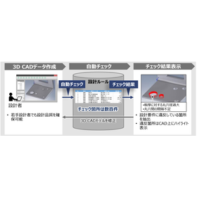
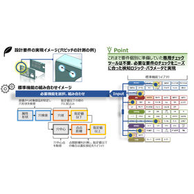
Achieve a reduction in design lead time through automatic checks of design rules!

The "Awareness Support CAD System" is a system that analyzes design data and the designer's operation history to detect potential issues and inefficient processes in real-time during the design process. By utilizing past design data and best practices, it provides specific improvement suggestions to designers. It automatically checks 3D CAD models based on design requirements (design rules and ease of processing). Compared to visual checks, it significantly reduces the time required for checks and rework. 【Features】 ■ Real-time problem detection ■ Utilization of knowledge base ■ Analysis of operation history ■ Collaboration features ■ Customizability *For more details, please download the PDF or feel free to contact us.

Added to bookmarks

Bookmarks list

Bookmark has been removed

Bookmarks list

You can't add any more bookmarks

By registering as a member, you can increase the number of bookmarks you can save and organize them with labels.

Free membership registration

[Case Study] Parts Processing (Design and Delivery Management Using 3D Data)

If you have concerns about part processing, from design (CAD and drafting) to delivery and installation, such as the centralization of 3D data design and deadline management, please contact us.

Our company develops, designs, and manufactures jigs, prototype equipment, and systems according to our customers' requests. We would like to introduce a case where we implemented our "design and delivery management using 3D data" for Company A, a manufacturer of automotive parts. At this company, processing parts based on 2D drawings was time-consuming and labor-intensive, and input errors were occurring. Additionally, the difficulties in delivery management due to individual ordering of materials and the complexity of adjustment tasks were problematic. Therefore, they requested our services to achieve integrated management of 3D data design and delivery management. As a result, input errors during parts processing were eliminated, the man-hours for creating drawings were reduced, and improvements in processing accuracy and overall efficiency of the processing process were achieved. Furthermore, the introduction of integrated management led to the consolidation of order quantities and increased efficiency in delivery management, reducing the workload for the responsible personnel. *For more details, please refer to the PDF document or feel free to contact us.

  • 3D CAD
  • soft

Added to bookmarks

Bookmarks list

Bookmark has been removed

Bookmarks list

You can't add any more bookmarks

By registering as a member, you can increase the number of bookmarks you can save and organize them with labels.

Free membership registration

Musculoskeletal modeling system "AnyBody"

Freely customize analysis models and output data! Software for analyzing muscle behavior.

"AnyBody" is software that analyzes muscle behavior, which is the source of human motion, using a human musculoskeletal model. It inputs movements obtained from measurements or movements defined by the user into a detailed musculoskeletal model, and calculates the muscle activity and muscle strength required to realize that movement, as well as various quantities generated within the human body (joint reaction forces, joint moments, energy consumption) through inverse dynamics analysis. Additionally, it can import 3D CAD shapes of industrial products and surrounding environments for analysis. 【Features】 ■ Highly reliable musculoskeletal model ■ Robustly solves complex movements/closed-loop conditions/indeterminate conditions ■ All input conditions and definitions are viewable and editable ■ Provides models as open source that can withstand extensive validation ■ Used as a tool by researchers worldwide and published in numerous research papers *For more details, please refer to the related links or feel free to contact us.

  • Mechanism Analysis
  • soft

Added to bookmarks

Bookmarks list

Bookmark has been removed

Bookmarks list

You can't add any more bookmarks

By registering as a member, you can increase the number of bookmarks you can save and organize them with labels.

Free membership registration

Real-time analysis software Creo Simulation Live

This is software that enables real-time simulation on the 3D CAD software "Creo," which designers are accustomed to using.

Designers can instantly check analysis results themselves, significantly reducing work time. By implementing Creo Simulation Live, real-time simulations can be performed based on CAD data, allowing designers to immediately verify analysis results on the spot. This virtually eliminates waiting time for analysis and greatly shortens the iteration time between design and analysis in the basic design phase.

  • Structural Analysis
  • Other CAD related software
  • simulator
  • soft

Added to bookmarks

Bookmarks list

Bookmark has been removed

Bookmarks list

You can't add any more bookmarks

By registering as a member, you can increase the number of bookmarks you can save and organize them with labels.

Free membership registration

Failures and successes of 3D implementation. Three candid case studies from the field available for free!

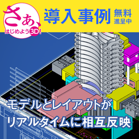
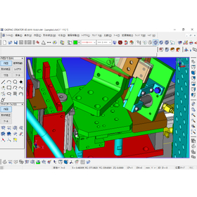
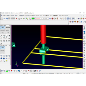
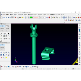
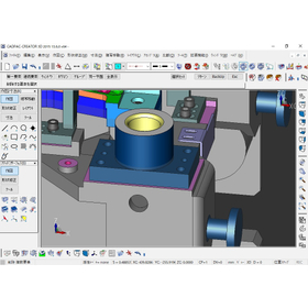
"Struggles with high-performance 3D" and "Exhausted from CATIA data modifications"... Presenting case studies from three companies that solved on-site issues! What is the design method that doesn't waste 2D assets?

Many sites face the "barrier of 3D conversion" and "data integration challenges." We are currently offering a free collection of case studies filled with specific episodes that have overcome these issues. This document includes the following three solution cases. ■ Overview of Case Studies 【Utilization of 2D Assets】 - A case study of a welding jig manufacturer that dramatically improved design efficiency by effectively utilizing past 2D drawing assets after initially failing with the introduction of a high-functionality constraint and history-type 3D CAD. 【CATIA Data Integration】 - A case study in press mold design that reduced "surface loss" and modification man-hours caused by IGES conversion when receiving CATIA data from clients, enabling direct editing of raw data. 【Reduction of Jig Creation Man-Hours】 - A case study where even those with no 3D experience or beginners intuitively created complex freeform plating jigs from provided 3D data, achieving 3D printing. Why is CADPAC chosen for its "intuitive operation" and "2D-like usability"? You will learn how to choose 3D tools that won't lead to failure. *For more details, please download the PDF or contact us directly.

  • Clipboard02.jpg
  • Clipboard05.jpg
  • Clipboard06.jpg
  • Clipboard03.jpg
  • 3D CAD
  • 2D CAD machine
  • Other CAD
  • soft

Added to bookmarks

Bookmarks list

Bookmark has been removed

Bookmarks list

You can't add any more bookmarks

By registering as a member, you can increase the number of bookmarks you can save and organize them with labels.

Free membership registration

Removing the barriers between designers and analysts: "Simcenter 3D"

It is a CAE tool that directly imports design data and handles coupled analysis (multiphysics) within a single framework.

"Simcenter 3D," a powerful tool that integrates CAE solutions from various specialized fields, can perform coupled analysis (multiphysics) simulations such as structural-fluid, structural-thermal, structural-thermal-fluid, and structural-mechanical analyses. It allows for the direct import of design data, mesh generation, and analysis all within a single framework. This is the digital tool of the future that removes the barriers between designers and analysts.

  • Plastic processing machines (cutting and rolling)
  • Analysis Services
  • soft

Added to bookmarks

Bookmarks list

Bookmark has been removed

Bookmarks list

You can't add any more bookmarks

By registering as a member, you can increase the number of bookmarks you can save and organize them with labels.

Free membership registration

Point cloud processing software "InfiPoints"

Point cloud processing software for engineering.

We handle the point cloud processing software "InfiPoints." You can view large volumes of point cloud data measured with a 3D laser scanner on your computer to check the site, create CAD models from the point cloud, and transfer them to BIM software or CAD, thereby streamlining traditional modeling tasks. This brings innovation to existing construction processes and simulation work. 【Features】 ■ Supports five processes: data loading, data preprocessing, simulation, modeling, and deliverable creation in a one-stop manner. ■ Streamlines and enhances the efficiency of preparatory work. ■ Integrates information from existing facilities into BIM. *For more details, please download the PDF or contact us.

Added to bookmarks

Bookmarks list

Bookmark has been removed

Bookmarks list

You can't add any more bookmarks

By registering as a member, you can increase the number of bookmarks you can save and organize them with labels.

Free membership registration

Sheet metal estimation software 'iQ3-SW' dedicated to SOLIDWORKS

List 3D modeling data by parts! Automatically calculated from various information and parameters.

The "iQ3-SW" is an estimation software that allows for 3D CAD cost simulation of sheet metal processing for multiple assembly products. It displays 3D modeling data in a parts list format. Automatic unfolding of sheet metal is performed for cost calculation. Additionally, welding instructions can be generated simply by clicking on the edges or surfaces of the 3D data. It automatically recognizes welding length, welding locations, and welding finishes. 【Features】 ■ Automatic calculations from various information and parameters ■ Understanding of time and cost by process ■ Automatic extraction, editing, and additional input of unfolded rectangular sizes and processing information ■ Standard cost parameters included * For more details, please refer to the PDF materials or feel free to contact us. * If you wish to request a demo, please do not hesitate to contact us via the "Contact Us" button below. Online or in-person visits are also possible.

Added to bookmarks

Bookmarks list

Bookmark has been removed

Bookmarks list

You can't add any more bookmarks

By registering as a member, you can increase the number of bookmarks you can save and organize them with labels.

Free membership registration