We have compiled a list of manufacturers, distributors, product information, reference prices, and rankings for soft.
ipros is IPROS GMS IPROS One of the largest technical database sites in Japan that collects information on.

soft(3D CAD) - List of Manufacturers, Suppliers, Companies and Products | IPROS GMS

Last Updated: Aggregation Period:Jul 29, 2026~Aug 25, 2026
This ranking is based on the number of page views on our site.

soft Product List

241~270 item / All 742 items

Displayed results

Autodesk Manufacturing Software Collection "PD&M Collection"

Contributing to solving various challenges in the manufacturing industry with a single package. Aggregating software suitable for sales, design, processing, and manufacturing.

The "Product Design & Manufacturing Collection (PD&M Collection)" is a product that combines approximately 20 software and tools corresponding to each process, from planning and design to analysis, plant design, manufacturing, and the creation of promotional tools, along with online storage. It enables the streamlining of each process, improvement of quality, and promotion of digitization and data integration. Please utilize it for efforts towards labor reduction and cost savings. 【We respond to the following needs】 ■ Want to create hidden lines quickly and accurately ■ Want to manage and share parts lists easily ■ Want to shorten the time for electrical design ■ Want to perform control design in compliance with standards ■ Want to reflect changes in design data to other data *For more details, please refer to the materials available for download in PDF format. Feel free to contact us as well.

  • Software (middle, driver, security, etc.)
  • soft

Added to bookmarks

Bookmarks list

Bookmark has been removed

Bookmarks list

You can't add any more bookmarks

By registering as a member, you can increase the number of bookmarks you can save and organize them with labels.

Free membership registration

Prevent design mistakes with interference checks!! 3DCAD "VariCAD"

Prevent design mistakes with interference checks!! 3D CAD "VariCAD"

Features of VariCAD products: - Easily check for interference by calculating the distance between solid models. - Interference points that are difficult to find in 2D drawings can be detected in 3D models, preventing setbacks in later manufacturing processes when interference is noticed. In addition to the interference check function, VariCAD includes various basic tools such as BOM creation, sheet metal unfolding, mechanical part calculation functions, and assembly functions, all available at a low price starting from around 130,000 yen including one year of support. Furthermore, for Ipros members who download the catalog, we are currently offering a discount coupon of 5,000 yen. *Download the 30-day free trial version here: https://varicad.add-soft.jp/download/

  • VariCAD2.png
  • VariCAD3.png
  • rendering1.png
  • rendering2.png
  • 3D CAD
  • 2D CAD machine
  • soft

Added to bookmarks

Bookmarks list

Bookmark has been removed

Bookmarks list

You can't add any more bookmarks

By registering as a member, you can increase the number of bookmarks you can save and organize them with labels.

Free membership registration

Problem-Solving Materials: Utilizing 3D Data Edition 8 | Software Implementation Costs and Learning Costs

What are the challenges to keep in mind when introducing reverse engineering for the first time to ensure success? A resource for identifying and solving issues in the production field.

This document is a series that proposes solutions to various challenges faced in the production field, from identifying issues to finding resolutions. In the "3D Data Utilization Edition," we introduce various solutions to manufacturing challenges through the use of 3D data. This document focuses on the theme of "Tips for Successfully Implementing Reverse Engineering for the First Time," highlighting key challenges and their solutions. [Document Overview] Reverse engineering utilizing 3D scanning is becoming widespread as an effective method for streamlining design and production processes. When introducing equipment, many people first pay attention to 3D scanners. However, even more critical for the success of reverse engineering is the "selection of software." This involves the challenges of "introducing software to create CAD data from 3D scan data" and "learning how to operate the software." This document explains the two challenges encountered when implementing reverse engineering. It introduces key points to consider initially in order to adopt a method suitable for your company. *You can download the document using the button below.

  • 3D CAD
  • Data conversion software
  • Other CAD related software
  • soft

Added to bookmarks

Bookmarks list

Bookmark has been removed

Bookmarks list

You can't add any more bookmarks

By registering as a member, you can increase the number of bookmarks you can save and organize them with labels.

Free membership registration

NC machine simulation software "VERICUT"

Identify mistakes and inefficient areas! Collisions in the "virtual machine" serve to protect the actual machines.

"VERICUT" is simulation software for G-code NC programs executed on machine tools. Before processing on machine tools, it verifies NC data created by CAM software on a PC. It reproduces the machine tool and its movements on the PC, preventing errors and troubles such as collisions caused by the program. By utilizing CAD data, it is also possible to conduct detailed inspections of leftover material and overcutting. 【Features】 ■ Supports simulation of "G-code NC programs" for various NC machine tools ■ Faithfully reproduces in-machine operations in detail ■ Reproduces all elements in 3D, detecting collisions and interferences ■ Significantly reduces verification work on actual machines, enabling quick start of processing ■ Reduces costs associated with machine damage and troubles *For more details, please refer to the PDF document or feel free to contact us.

Added to bookmarks

Bookmarks list

Bookmark has been removed

Bookmarks list

You can't add any more bookmarks

By registering as a member, you can increase the number of bookmarks you can save and organize them with labels.

Free membership registration

VR launcher software "EasyVR"

No data conversion needed! A groundbreaking software that easily enables VR display.

"EasyVR" can automatically convert your 3D CAD/CAE software into VR. By analyzing the drawing output of general-purpose 3D application software (such as CAD/CAM/visualization) and adding virtual reality processing, it can reconstruct the drawing output in real-time as a virtual reality space while the application software is running. 【Features】 ■ Reduction of monetary costs ■ No need for data conversion ■ Results of operations are reflected in the VR space in real-time ■ Accuracy depends on the display of the 3D application ■ No decrease in accuracy due to data conversion *For more details, please refer to the PDF materials or feel free to contact us.

  • Software (middle, driver, security, etc.)
  • Virtual Reality Related
  • others
  • soft

Added to bookmarks

Bookmarks list

Bookmark has been removed

Bookmarks list

You can't add any more bookmarks

By registering as a member, you can increase the number of bookmarks you can save and organize them with labels.

Free membership registration

Case Presentation: Initiatives to Shorten Manufacturing Lead Time by Over 30% Without 2D Drawings

With "meviy," the machine parts procurement service provided by Misumi, and "iCAD SX," the 3D CAD software offered by Fujitsu, parts arrangement can be done in just one minute!

\ Iprosu members can get case studies without registration / What initiatives has the professional group Abirika, specializing in production equipment design, implemented to achieve a "30% or more reduction in manufacturing lead time"? Please obtain it from the black button "PDF Download" in the upper right. Are you creating 2D drawings for processing instructions even though you are designing in 3D CAD? While the adoption of 3D technology in mechanical design is progressing, many procurement processes still rely on paper drawings, and existing practices are hindering productivity improvements. The 3D CAD "iCAD SX," specialized in mechanical design, and the online mechanical parts procurement service "meviy" have begun collaboration. By uploading a 3D model created in iCAD, the hole attribute information is automatically reflected in meviy, allowing for a quotation of mechanical parts in just one minute. This significantly reduces the time-consuming tasks of creating 2D drawings and obtaining estimates, greatly improving design quality and work efficiency. For details and case studies, please click the link below. ↓ ↓ ↓

Added to bookmarks

Bookmarks list

Bookmark has been removed

Bookmarks list

You can't add any more bookmarks

By registering as a member, you can increase the number of bookmarks you can save and organize them with labels.

Free membership registration

Problem-Solving Materials: Utilizing 3D Data Part 6 | Shortening the Development Cycle

Reduce the costs associated with prototyping! How to effectively utilize two prototyping tools? A resource for discovering and solving challenges in the production site.

This document is a series that proposes solutions for various challenges faced in production sites, from identifying issues to finding solutions. In the "3D Data Utilization Edition," we will introduce various solutions to manufacturing challenges through the use of 3D data. In Vol. 6, we will focus on "Shortening the Development Cycle" and discuss improvements in the prototyping process using 3D modeling tools. [Document Overview] The internalization of the prototyping process is making significant progress alongside the trend of shortening product development cycles, such as reducing the number of prototypes through the use of CAD and CAE analysis. However, in prototyping with widely used 3D printers, we often hear about challenges such as: - Inability to evaluate with desired materials - Dissatisfaction with precision - Excessive costs for maintaining equipment To address these challenges, an increasing number of people are considering the use of "modeling machines." This document introduces the features of "3D modeling tools" that achieve cost reduction and shorten the development process. It explains the scenarios in which the two tools, 3D printers and modeling machines, excel and struggle. *You can download the document using the button below.

  • Grinding Machine
  • others
  • soft

Added to bookmarks

Bookmarks list

Bookmark has been removed

Bookmarks list

You can't add any more bookmarks

By registering as a member, you can increase the number of bookmarks you can save and organize them with labels.

Free membership registration

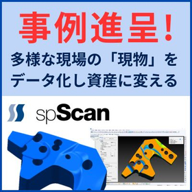
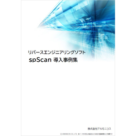
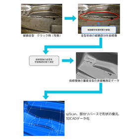
Streamlining Supply Production: Mold Restoration with Reverse Engineering Software

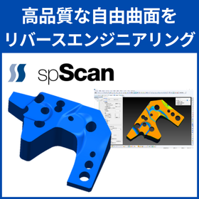
Significantly reduce the man-hours for automobile development! A reverse engineering tool dedicated to accurately CAD modeling complex freeform surfaces, "spScan."

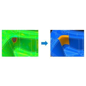
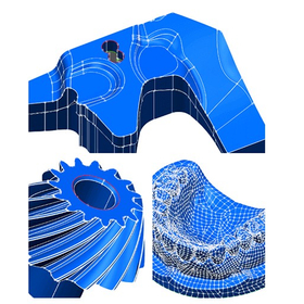
This is a dedicated tool for creating high-quality NURBS surfaces from 3D point cloud and polygon data obtained by non-contact scanners, making it easy to utilize in design and analysis. It excels in modeling complex freeform surfaces, such as automotive bodies and interior components, achieving smooth surface compositions with fewer control points in a short amount of time. 【Use Cases】 - CAD conversion of design clay models In the early stages of development, where shape changes are frequent, it quickly creates high-precision surface data from actual clay models, streamlining design considerations and component layout evaluations. - Feedback of hand-finished mold shapes to design The "partial reverse" function allows for the extraction of only the areas adjusted or modified by craftsmen on-site, enabling minimal effort to reflect these changes in existing CAD data. - Restoration of molds for spare parts and competitive analysis Scanning actual parts from discontinued vehicles or products from other companies and converting them to CAD data for use in remaking spare parts or benchmark analysis. 【Benefits of Implementation】 By allowing modeling while checking for discrepancies with design data, it reduces rework. The created data can be output in common formats such as IGES and STEP, making it usable in subsequent CAD/CAM/CAE systems.

  • Other CAD related software
  • soft

Added to bookmarks

Bookmarks list

Bookmark has been removed

Bookmarks list

You can't add any more bookmarks

By registering as a member, you can increase the number of bookmarks you can save and organize them with labels.

Free membership registration

3D Viewer Software for Mold Manufacturing: 3DTascalX Series

Quickly check necessary information for mold manufacturing such as "data conversion, undercut, processing/inspection dimensions"! To reduce the time spent waiting and rework in creating 2D drawings.

The "3DTascalX series" is a 3D CAD viewer software that allows easy access to the information needed during mold manufacturing. It supports not only CAD data from CATIA, NX, Creo, SOLIDWORKS, and Inventor, but also almost all 3D data available in the market, including intermediate data formats such as IGES, STEP, Parasolid, ACIS, and JT. There are many features available for "mold manufacturing": For design → data conversion, healing For processing → auxiliary coordinate setting, 3D sketch (material shape), high-precision measurement, 2D drawing For inspection → probe coordinate setting, actual measurement input, error determination 【Features】 ■ Suitable for mold drawing-less projects ■ Enables acquisition of necessary information on-site, simplifying 2D drawings ■ Reduces waiting and rework time with high-precision and quick checks ■ Additional functions for inspection departments ■ Can be distributed to clients with a free viewer *For more details, please refer to the materials. Feel free to contact us with any inquiries.

  • Data conversion software
  • Press Dies
  • Mold Design
  • soft

Added to bookmarks

Bookmarks list

Bookmark has been removed

Bookmarks list

You can't add any more bookmarks

By registering as a member, you can increase the number of bookmarks you can save and organize them with labels.

Free membership registration

Problem-Solving Materials: 3D Data Compatibility Edition 2 | Cost of 3D CAD/CAM

What are the challenges of introducing and operating 3D CAD/CAM costs, and how can they be resolved? A resource for identifying and solving issues in the production field.

This document is a series that proposes solutions to various challenges faced in production sites, from identifying issues to finding resolutions. In the [3D Data Compatibility Edition], we will introduce solutions aimed at addressing the challenges of "adapting to 3D data." [Document Overview] With the expansion of design and development based on 3D data, the utilization of 3D data in production sites is more essential than ever. By utilizing 3D CAD/CAM, it is possible to create programs more efficiently than traditional methods. However, many may be struggling with the balance between cost and functionality, facing issues such as: - Higher initial costs compared to 2D CAD/CAM - Unnecessarily high operational costs - Concerns that low-cost products may lack necessary features Therefore, in this document, we will introduce recommended 3D CAD/CAM solutions that allow for the selection and implementation of necessary features while minimizing both initial and operational costs. We will also explain functionalities that contribute to improving operational efficiency. *You can download the document using the button below.

  • 3D CAM
  • 2D CAM
  • Other CAM related software
  • soft

Added to bookmarks

Bookmarks list

Bookmark has been removed

Bookmarks list

You can't add any more bookmarks

By registering as a member, you can increase the number of bookmarks you can save and organize them with labels.

Free membership registration

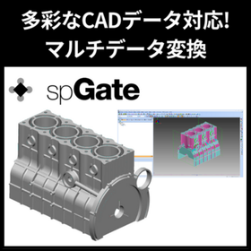
Organizing CAD data into a format that makes it easy to convert to NC data! Utilizing spGate.

Data conversion and modification software that serves as a bridge from CAD to CAM.

To smoothly generate NC data with CAM, the quality and format of the underlying CAD data are extremely important. spGate can be utilized as a data conversion and modification software that bridges CAD and CAM. If the 3D model received from the design department contains issues such as the following, it can lead to problems during the machining stage: - Gaps in surfaces or discontinuous edges - Irregular curvature or distorted surfaces - High-density surfaces with too many control points These issues can cause abnormal behavior or disruptions in the tool path generation in CAM, posing a risk of decreased accuracy of NC data and machining quality. spGate detects these problems in advance and automatically performs healing processes. Furthermore, it can automate conversion and modification processes through batch execution, allowing for efficient processing of multiple CAD data and reducing rework on the shop floor. We have introduced actual cases where the implementation of spGate significantly reduced troubles in NC data creation on the following page. Please take a look.

  • Data conversion software
  • soft

Added to bookmarks

Bookmarks list

Bookmark has been removed

Bookmarks list

You can't add any more bookmarks

By registering as a member, you can increase the number of bookmarks you can save and organize them with labels.

Free membership registration

3D Data Management PDM Software SearchManager Pro2

Ready to use! 3D CAD data management features

3D Data Management PDM Software SearchManager Pro2 SearchManager Pro2 automatically applies exclusive control to related files when sharing and using 3D data on servers, eliminating opportunities for loss in design operations. It can automatically analyze assembly files from SOLIDWORKS and CADSUPER Works, checking in and out related sub-assembly and part files in bulk. For estimates or any inquiries, please feel free to contact us. ■ Contact Information Marble Inc. Embedded Product Division, Product Business Department Phone: (03) 3419-6011

Added to bookmarks

Bookmarks list

Bookmark has been removed

Bookmarks list

You can't add any more bookmarks

By registering as a member, you can increase the number of bookmarks you can save and organize them with labels.

Free membership registration

BUNSHIN: Realizing the efficiency of equipment moving operations.

By fully digitizing the factory with 3D scanning, we can simulate the loading and unloading operations of equipment, achieving greater efficiency in the work process.

"BUNSHIN" digitizes the entire factory through 3D scanning of the actual site, enabling various solutions such as simulations for equipment installation and layout changes by merging with 3D CAD models. It is a new system that meets the demands of the era, such as digital transformation (DX) and remote capabilities. During the COVID-19 pandemic, the introduction of large machinery to factories required many stakeholders to gather on-site for work discussions. By utilizing "BUNSHIN," it is possible to gather online as many times as needed in the digitized factory to simulate the addition, movement, or removal of equipment, leading to reductions in processes and costs through the digital transformation of factory equipment installation and layout changes. **Features of BUNSHIN:** - Digitization through 3D scanning of the actual site - Editable 3D scan data! - Possible integration with CAD data! - Recreate the site online and reduce business trips!

  • Other operation management software
  • soft

Added to bookmarks

Bookmarks list

Bookmark has been removed

Bookmarks list

You can't add any more bookmarks

By registering as a member, you can increase the number of bookmarks you can save and organize them with labels.

Free membership registration

SOLIDWORKS Application Examples

We are offering a catalog that clearly presents case studies, benefits, and detailed features for those considering transitioning from 2D to 3D!

Digital design services provide the product design tool "3D CAD/SOLIDWORKS," which combines ease of use, functionality, and implementation costs. This catalog includes case studies of SOLIDWORKS used in various scenarios, as well as details on its benefits and the latest version features. "For those who want to switch from their current tools to a different one" or "for those who want to implement 3D CAD," we propose the most suitable tools for your business and environment, and we support you with a series of requests from operational methods after implementation to maintenance. [Contents] ■ Case Studies ■ SOLIDWORKS Feature Details Product Design / Design Verification / Product Data Management / Communication / Electrical Design *For more details, please refer to the PDF document or feel free to contact us.

Added to bookmarks

Bookmarks list

Bookmark has been removed

Bookmarks list

You can't add any more bookmarks

By registering as a member, you can increase the number of bookmarks you can save and organize them with labels.

Free membership registration

Simpleware Software

Support for creating models from physical objects! Providing world-class software solutions.

Simpleware Software assists in creating models from physical objects and can be utilized for applications in analysis and feedback for development. It provides a wide range of solutions, including the creation of high-quality meshes and the output of CAD data without the need for an intermediate format from complex 3D image data. Meshes can be created from 3D images such as X-ray CT, MRI, and SEM, as well as from STL files obtained from non-contact 3D measurement devices, making it useful for analysis, design, and research and development. [Features (partial)] ■ Supports a wide variety of input and output formats ■ Reduces image noise through filtering ■ Automatically performs segmentation by specifying the number of extraction categories ■ Easily extracts continuous and closed regions ■ Extracts each region by specifying grayscale thresholds *For more details, please refer to the PDF document or feel free to contact us.

  • Image analysis software
  • soft

Added to bookmarks

Bookmarks list

Bookmark has been removed

Bookmarks list

You can't add any more bookmarks

By registering as a member, you can increase the number of bookmarks you can save and organize them with labels.

Free membership registration

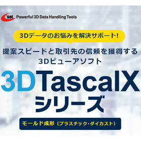
Viewer software for mold forming: "3DTascalX Series"

Instantly grasp shapes such as "clamping force, undercut, slope, and wall thickness"! Reducing man-hours for creating 2D drawings and estimating costs. Over 3,000 companies have adopted it in Japan.

The "3DTascalX series" is a 3D CAD viewer software that allows users to easily obtain the information needed on-site. It supports not only CAD data from CATIA, NX, Creo, SOLIDWORKS, and Inventor but also nearly all 3D data formats in circulation, including intermediate data such as IGES, STEP, Parasolid, ACIS, and JT. It also includes features useful for the "mold manufacturing" industry. It supports maximum outer dimensions, weight calculations, clamping force, slope, wall thickness, undercuts, color coding of design change areas, and the creation of 2D drawings such as three-view drawings, isometric drawings, and cross-sectional views. 【Features】 ■ Obtain necessary information on-site and simplify 2D drawings ■ Achieve high precision and quick estimate responses to prevent loss of opportunities ■ Reduce waste in operations such as waiting and rework ■ Optimize the running costs of 3D CAD *For more details, please refer to the materials. Feel free to contact us with any inquiries.

  • Data conversion software
  • plastic
  • Other polymer materials
  • soft

Added to bookmarks

Bookmarks list

Bookmark has been removed

Bookmarks list

You can't add any more bookmarks

By registering as a member, you can increase the number of bookmarks you can save and organize them with labels.

Free membership registration

CAM software "SolidCAM" comprehensive catalog

Fully integrated SolidWorks CAM software that allows direct CNC programming on SolidWorks design data!

"SolidCAM" is a CAM software that is fully integrated with "SolidWorks," allowing direct CNC programming on SolidWorks design data. This eliminates the need for loading and conversion tasks, significantly reducing labor hours. CAD features can be used as they are, making it easy for beginners to handle design changes and edit single-side intersections. *Currently, we are offering a comprehensive catalog as a gift! 【Features】 ■ Processing data linked to model changes ■ Design of fixtures and clamp layouts using assembly functions ■ Editable in a single window ■ 70% reduction in processing time and extended tool life through high-efficiency machining with "iMachining" *For more details, please request materials or view the PDF data available for download.

  • Other CAM related software
  • soft

Added to bookmarks

Bookmarks list

Bookmark has been removed

Bookmarks list

You can't add any more bookmarks

By registering as a member, you can increase the number of bookmarks you can save and organize them with labels.

Free membership registration

Rome Co., Ltd. [3D CAD Implementation Case] i CAD SX

Improve the development speed of semiconductor component manufacturing lines! Achieve quality enhancement with 3D CAD.

We would like to introduce a case study of business improvement using the 3D CAD specialized in mechanical design, "iCAD SX." At "Rohm Co., Ltd.," they have been internalizing semiconductor manufacturing equipment and have been working for many years to transition to 3D design in order to reduce interference and assembly issues. After careful consideration, they initially introduced a 3D CAD but abandoned its operation. They pointed out issues such as the difficulty in handling models due to strict rules when attempting team design, and that it took over 30 minutes to display files for 2,000 parts. Seeking "flexible team design" and "operability and speed akin to drawing with a pencil on paper," they selected "iCAD SX" and successfully improved business efficiency through 3D design. 【Main Effects of Implementation】 - Streamlining of upstream design processes and reduction of design development time - Activation of design reviews with related departments due to improved visibility of drawings - Interference suppression and reduction of man-hours through motion simulation of 6-axis robots 【Download Materials】 - Currently available for limited access on the special website. Please click the link below.    ▼▼▼ Click here ▼▼▼

Added to bookmarks

Bookmarks list

Bookmark has been removed

Bookmarks list

You can't add any more bookmarks

By registering as a member, you can increase the number of bookmarks you can save and organize them with labels.

Free membership registration

Introduction to Desktop Structural Analysis Program

Creating geometry and analysis models, executing analyses, and post-processing, all realized in one software!!

【Features】 ○ A structural analysis solution that combines the pre- and post-processor "Simcenter Femap" with the analysis solver "Simcenter Nastran." ○ The entire process of creating analysis models, performing analyses, and displaying results from shape data created in 3D-CAD is realized in one software on a single PC. ○ High operability. ○ Easy to implement pricing. ◎ For more detailed information, please refer to the catalog or contact us directly.

  • Structural Analysis
  • soft

Added to bookmarks

Bookmarks list

Bookmark has been removed

Bookmarks list

You can't add any more bookmarks

By registering as a member, you can increase the number of bookmarks you can save and organize them with labels.

Free membership registration

AI software "ARUMCODE1" for cutting processing companies.

Just load the CAD data! The NC program settings for machining are fully automated! The estimated cost per drawing is also calculated automatically!

"ARUMCODE1" is an AI software that analyzes the shape of 3D CAD data and automatically outputs NC programs. With just one click, the analysis starts, and the NC program is completed in a short time. Since it only requires loading CAD data, the burden on operators is also reduced. Additionally, it is packed with useful features such as work instructions, process charts, and estimates, in addition to the automatic output of NC programs. There is also a subscription version called "ARUM Factory365" that keeps initial costs low during implementation. 【Features】 ■ NC programs are completed in a short time ■ Reduces the burden on operators as it only requires loading CAD data ■ Automatically calculates estimated costs per drawing ■ Promotes cost reduction and productivity improvement within the factory ■ Packed with useful features beyond automatic output of NC programs *For more details, please refer to the PDF materials or feel free to contact us.

  • Software (middle, driver, security, etc.)
  • soft

Added to bookmarks

Bookmarks list

Bookmark has been removed

Bookmarks list

You can't add any more bookmarks

By registering as a member, you can increase the number of bookmarks you can save and organize them with labels.

Free membership registration

Five Reasons Why hyperMILL is Chosen

Achieve ideal simultaneous 5-axis machining! Quickly and safely process 2-axis machining with intuitive operation!

This document is intended for customers considering CAD/CAM software, specifically those considering "hyperMILL." We will introduce the reasons why our product is chosen among many CAD/CAM software options. We hope this information will be helpful in your software evaluation. [Contents] - Ideal 5-axis machining with simple operation - Automation of program creation - 2-axis machining utilizing 3D data - Reduced machining time with barrel tools - Machine simulation based on NC *For more details, please refer to the PDF document or feel free to contact us.

Added to bookmarks

Bookmarks list

Bookmark has been removed

Bookmarks list

You can't add any more bookmarks

By registering as a member, you can increase the number of bookmarks you can save and organize them with labels.

Free membership registration

I tried making a 3D printed jig from the drawing!

[Mitarepo] I tried making a 3D printed jig from a drawing! Jig creation software "EZ Jig for Rhino" | System Create

Mitarepo is a series that introduces what can be done using various products with the concept of "I tried doing this!" We are excited to announce the debut of a new jig creation software, "EZ jig for Rhino"! Even those who have never operated CAD before can easily create 3D data for jigs by simply following the on-screen wizard! Since it is based on drawing data, it requires minimal effort and fits perfectly! However, we are curious whether it can create jigs that improve work efficiency on-site... So this time, we borrowed the product part data from one of our partner companies that is actually using jigs for assembly, and we tested whether we could create a jig that meets the requirements! "Can anyone do this easily?" "Can I model a 3D object from a drawing?" We will explain these points of interest along with the flow of data creation, the 3D printing process, and images of the completed jigs. *You can download the materials from the button below.

  • jig
  • Processing Jig
  • Inspection fixture
  • soft

Added to bookmarks

Bookmarks list

Bookmark has been removed

Bookmarks list

You can't add any more bookmarks

By registering as a member, you can increase the number of bookmarks you can save and organize them with labels.

Free membership registration

VISI Machining: CAM Software

Design and manufacturing support! Providing world-class CAD/CAM solutions since 1988!

"VISI Machining" provides all the solutions necessary to achieve increased productivity, maximized cutting capabilities, and shortened delivery times. VISI creates intelligent tool paths even for complex 3D data. With its unique high-speed cutting technology and embedded smoothing algorithms, it generates efficient NC data, reducing the cycle time of machining equipment and enabling the continuous production of high-quality products. [Features] - Design and manufacturing support - Provides stable and powerful solid and surface modeling capabilities - A combination of Hexagon's surface technology, model analysis functions, and 2D drafting capabilities - Flexibly accommodates the construction, editing, and modification of complex 3D data - Offers practical, intuitive, and simple solutions for 2-axis machining programming, including multi-axis indexing *For more details, please refer to the PDF materials or feel free to contact us.

  • Other CAD related software
  • Other CAM related software
  • Other CAD
  • soft

Added to bookmarks

Bookmarks list

Bookmark has been removed

Bookmarks list

You can't add any more bookmarks

By registering as a member, you can increase the number of bookmarks you can save and organize them with labels.

Free membership registration

Integrated Multiphysics Analysis Software

Equipped with high-end meshing technology!

Our company offers "integrated multiphysics analysis software." It enables everything from shape creation using CAD to evaluation of calculation results in one package. All data is managed in a single file. Additionally, it allows for simultaneous analysis of multiple physical phenomena. It is suitable for cases where you want to add analysis to thermal fluid analysis. 【Features】 ■Integrated Environment - Achieves everything from shape creation using CAD to evaluation of calculation results in one package - Manages all data in a single file ■Multiphysics Support - Allows simultaneous analysis of multiple physical phenomena - Suitable for cases where you want to add analysis to thermal fluid analysis *For more details, please download the PDF or feel free to contact us.

  • Other CAD related software
  • soft

Added to bookmarks

Bookmarks list

Bookmark has been removed

Bookmarks list

You can't add any more bookmarks

By registering as a member, you can increase the number of bookmarks you can save and organize them with labels.

Free membership registration

[Information] Overview of the CAD/CAM Integrated EDA Tool 'START'

Towards a more global all-in-one tool! Design and edit with programming, new three-dimensional wiring design.

This document introduces an overview of "START," an original design tool specifically developed in Japan for manufacturing electronic devices that can be used in a Windows environment. It includes "CAE (analysis tools)," "START all-in-one flow," "integration map," and more. Please take a moment to read it. 【Function Overview】 ■ Creation of manufacturing data for TEG implementation evaluation boards ■ 3D wiring & check mold injection deflection reverse correction with Wybon ■ Open database & programming language implementation ■ 3D review using a free viewer *For more details, please refer to the PDF document or feel free to contact us.

  • 2D CAD Electrical
  • soft

Added to bookmarks

Bookmarks list

Bookmark has been removed

Bookmarks list

You can't add any more bookmarks

By registering as a member, you can increase the number of bookmarks you can save and organize them with labels.

Free membership registration

Metal Press Molding Viewer Software "3DTascalX Series"

Instantly grasp shapes such as 'welding points, negative angles, cross-sections, and line length measurements'! Reducing man-hours for creating 2D drawings and estimating costs. Over 3,000 companies have adopted it domestically.

The "3DTascalX series" is a 3D CAD viewer software that allows users to easily obtain the information needed during metal press molding. It supports not only CAD data from CATIA, NX, Creo, SOLIDWORKS, and INVENTOR but also almost all 3D data formats in circulation, including intermediate data such as IGES, STEP, Parasolid, ACIS, and JT. It also includes features useful for the "metal press molding" industry. It supports the creation of 2D drawings such as welding points, cross-section lines, negative angles, line length measurements, parts lists, color coding of design changes, and three-view drawings and cross-sections. 【Features】 ■ Enables the acquisition of necessary information on-site, simplifying 2D drawings ■ Achieves high precision and quick estimation responses to prevent opportunity loss ■ Reduces waste in operations such as waiting and rework ■ Optimizes the running costs of 3D CAD *For more details, please refer to the materials. Feel free to contact us with any inquiries.

  • Data conversion software
  • soft

Added to bookmarks

Bookmarks list

Bookmark has been removed

Bookmarks list

You can't add any more bookmarks

By registering as a member, you can increase the number of bookmarks you can save and organize them with labels.

Free membership registration

Crowd flow simulation software "MassMotion"

Recommended for safe building design and smooth facility operation. It predicts pedestrian movement routes and identifies conditions and density for congestion occurrence.

Software for simulating and analyzing how many pedestrians move within buildings, what routes each person chooses, and where congestion occurs as a result. By defining individual agendas and personalities for each pedestrian model moving within 2D/3D CAD models, it is possible to conduct very realistic pedestrian flow simulations, as each pedestrian model independently selects routes and behaves accordingly. This can be utilized in various architectural designs, disaster simulations, and redevelopment of existing facilities.

  • simulator
  • soft

Added to bookmarks

Bookmarks list

Bookmark has been removed

Bookmarks list

You can't add any more bookmarks

By registering as a member, you can increase the number of bookmarks you can save and organize them with labels.

Free membership registration

[Aspace Enterprise Use Case] Business Support

AR services for employees of companies! Customizable for relevant fields.

We would like to introduce a case study on how our product "Aspace Enterprise" is utilized for business support for employees in the maintenance, preservation, and maintenance departments. It is an easy-to-use scenario-based AR solution that facilitates support for maintenance operations, preservation, and assembly processes, achieving "object recognition" and "spatial recognition." Additionally, it can be customized for fields related to maintenance and repair work. 【Case Overview】 ■ Implemented System - 3D-AR CAD/VPS recognition scenario-driven - 3D-AR image AI integration *For more details, please download the PDF or feel free to contact us.

  • 1.PNG
  • 2.PNG
  • Software (middle, driver, security, etc.)
  • soft

Added to bookmarks

Bookmarks list

Bookmark has been removed

Bookmarks list

You can't add any more bookmarks

By registering as a member, you can increase the number of bookmarks you can save and organize them with labels.

Free membership registration

Proposal from the Design Department: "Fluid Analysis" Quality Improvement and Lead Time Reduction

We can solve the quality issues of "warpage" and "shrinkage" in injection molded products.

We provide optimal results throughout the entire process from the design stage to molding, using high-precision analysis technology. Issues such as "warpage" and "shrinkage" in injection-molded products can be addressed with improvement proposals using flow analysis software. We can accommodate products both before and after mold construction. 【Software Used】 - SolidWorks (3D CAD) - 3D-TIMON (flow analysis software) 【Examples of Proposals】 - Suggestions for ribbing shapes - Suggestions for gate positions - Proposals for the number and types of gates, etc. *For more details, please download the PDF or feel free to contact us.

  • Contract manufacturing
  • soft

Added to bookmarks

Bookmarks list

Bookmark has been removed

Bookmarks list

You can't add any more bookmarks

By registering as a member, you can increase the number of bookmarks you can save and organize them with labels.

Free membership registration