We have compiled a list of manufacturers, distributors, product information, reference prices, and rankings for soft.
ipros is IPROS GMS IPROS One of the largest technical database sites in Japan that collects information on.

soft(cam) - List of Manufacturers, Suppliers, Companies and Products | IPROS GMS

Last Updated: Aggregation Period:Jul 29, 2026~Aug 25, 2026
This ranking is based on the number of page views on our site.

soft Product List

91~120 item / All 797 items

Displayed results

Mechanical Cam Design and Manufacturing Support Software

Cam and gear software

"Mechanical_Cam" is software that assists in the design and production of plate cams and groove cams, allowing for the combination of five types of link mechanisms: linear end, rocking end, radial method, tangent method, and sine method, based on the basic cam mechanism. It also enables the creation of timing diagrams and the generation of cam curves using 21 types of cam profiles, in addition to universal curves. Furthermore, it can calculate cam contour errors and determine optimal cam contour coordinates. The created mechanism data and timing curve data can be saved to files. It supports the design and production of plate cams, groove cams, and internal cams by allowing the saving of tool center and contour coordinate data of the designed shapes in text files or DXF files.

  • Other CAD
  • Power Transmission Equipment
  • Assembly Machine
  • soft

Added to bookmarks

Bookmarks list

Bookmark has been removed

Bookmarks list

You can't add any more bookmarks

By registering as a member, you can increase the number of bookmarks you can save and organize them with labels.

Free membership registration

Barrel Cam Design and Manufacturing Support Software

Index Barrel Cam (Cylindrical Groove Cam) Design and Manufacturing Support Software

"Barrel_Cam" is software that supports the design and manufacturing of index barrel cams. 1. Allows selection of cam curves from 21 types of cam curves and universal curves. 2. Creates and displays graphs of displacement, velocity, acceleration, and inertial torque of the cam curve. 3. Designs relief (escape) for the groove entrances at both ends of the cam. 4. Enables the setting of cam follower handover. 5. Performs coordinate calculations using tool diameter correction functions based on tool diameter input. 6. Calculates and displays errors from linear interpolation of the cam profile. 7. Can design multi-groove barrel cams. 8. Can design right-hand and left-hand twisted barrel cams. 9. Displays the cam's rotation and engagement pressure angle and curvature radius in real time. 10. Saves tool center coordinate data (X, Y, A) in text file format. 11. Saves DXF files of cam diagrams, output spider diagrams, and assembly drawings. 12. Includes BMP file saving for drawing images and partial zoom functionality. 13. Displays and prints design data and cam curve graphs. 14. Creates modeling DXF data for FreeCAD.

  • Other CAD related software
  • soft

Added to bookmarks

Bookmarks list

Bookmark has been removed

Bookmarks list

You can't add any more bookmarks

By registering as a member, you can increase the number of bookmarks you can save and organize them with labels.

Free membership registration

Five Reasons Why hyperMILL is Chosen

Achieve ideal simultaneous 5-axis machining! Quickly and safely process 2-axis machining with intuitive operation!

This document is intended for customers considering CAD/CAM software, specifically those considering "hyperMILL." We will introduce the reasons why our product is chosen among many CAD/CAM software options. We hope this information will be helpful in your software evaluation. [Contents] - Ideal 5-axis machining with simple operation - Automation of program creation - 2-axis machining utilizing 3D data - Reduced machining time with barrel tools - Machine simulation based on NC *For more details, please refer to the PDF document or feel free to contact us.

Added to bookmarks

Bookmarks list

Bookmark has been removed

Bookmarks list

You can't add any more bookmarks

By registering as a member, you can increase the number of bookmarks you can save and organize them with labels.

Free membership registration

Vericut Optimizer Optimization that anyone can do

The optimized NC program is efficient. It significantly improves processing efficiency, reduces material waste, and accelerates the time to market for parts.

**Main Benefits of Vericut Optimizer** Vericut Optimizer is an NC program optimization solution that can operate independently without using Vericut. Even if you are satisfied with your current CAM verification software and have no intention of purchasing Vericut, Vericut Optimizer is the optimal choice.

  • simulator
  • soft

Added to bookmarks

Bookmarks list

Bookmark has been removed

Bookmarks list

You can't add any more bookmarks

By registering as a member, you can increase the number of bookmarks you can save and organize them with labels.

Free membership registration

"CAM promotional DVD" and "case studies" giveaway!

[Limited to 50 people] CAM promotion DVD and case study booklet giveaway! Processing chips are also being offered in a case.

Save up to 70% of processing time, dramatically increase tool life, and provide significant profit gains! 'iMachining' minimizes cycle time, and the association with roughing and finishing processes reduces programming time. Additionally, tools with more cutting edges allow for greater depth of cut and manage chip thickness to suppress tool chatter, thereby extending tool life. 【Info-box】 ● Promotional brochure ● iMachining chips (plastic case) ● Promotional videos (contents) - iMachining explanation PowerPoint video - iMachining machining video - SolidCAM operation video - SolidCAM demo version (SolidCAM can be operated if SolidWorks is available) - Simple operation manual *For more details, please download and take a look. If you would like a case study box, please contact us to let us know.

Added to bookmarks

Bookmarks list

Bookmark has been removed

Bookmarks list

You can't add any more bookmarks

By registering as a member, you can increase the number of bookmarks you can save and organize them with labels.

Free membership registration

CAD/CAM Integration Data Conversion Software [START]

Data conversion software with rich input/output and editing functions that can interface with the next process using appropriate data.

Input of Gerber/DXF/ODB++/GDS2/DSN/BMP/STL Output of Gerber/DXF/ODB++/GDS2/IDF/AIF/BMP/ANF/XFL/LAY is possible, and the input data can be edited and output as data suitable for manufacturing or simulation. Device data from different manufacturing processes can be consolidated onto the same sheet, and devices with significantly different unit systems can also be synthesized. Differences in data components (such as polygon patterns, line widths, custom pads, etc.) can be smoothly imported and matched.

  • Data conversion software
  • 2D CAD Electrical
  • 2D CAM
  • soft

Added to bookmarks

Bookmarks list

Bookmark has been removed

Bookmarks list

You can't add any more bookmarks

By registering as a member, you can increase the number of bookmarks you can save and organize them with labels.

Free membership registration

NC machine simulation software "VERICUT"

Identify mistakes and inefficient areas! Collisions in the "virtual machine" serve to protect the actual machines.

"VERICUT" is simulation software for G-code NC programs executed on machine tools. Before processing on machine tools, it verifies NC data created by CAM software on a PC. It reproduces the machine tool and its movements on the PC, preventing errors and troubles such as collisions caused by the program. By utilizing CAD data, it is also possible to conduct detailed inspections of leftover material and overcutting. 【Features】 ■ Supports simulation of "G-code NC programs" for various NC machine tools ■ Faithfully reproduces in-machine operations in detail ■ Reproduces all elements in 3D, detecting collisions and interferences ■ Significantly reduces verification work on actual machines, enabling quick start of processing ■ Reduces costs associated with machine damage and troubles *For more details, please refer to the PDF document or feel free to contact us.

Added to bookmarks

Bookmarks list

Bookmark has been removed

Bookmarks list

You can't add any more bookmarks

By registering as a member, you can increase the number of bookmarks you can save and organize them with labels.

Free membership registration

Parallel Cam Design and Manufacturing Support Software Para_Cam

Index Parallel Cam Design and Manufacturing Support Software

The parallel cam design and manufacturing support software is a tool that assists in the design and production of index parallel cam mechanisms. It allows the selection of cam curves from 21 types of cam profiles and universal curves. You can change the dimensionless time parameters of the cam curves. It creates and displays graphs of displacement, velocity, acceleration, and inertial torque of the cam curves. It includes design modifications for the cam tip (relief) and the cam base (relief). It performs coordinate calculations using a tool diameter correction function based on input tool diameter. It calculates and displays errors from linear interpolation of the cam profile. It can design both one-turn and half-turn parallel cams. The rotation of the cam and the engagement pressure angle and curvature radius are displayed in real-time. Tool center coordinate data (X, Y) can be saved in text file format. Cam drawings, output slider diagrams, and assembly drawings can be saved as DXF files. Drawing images can be saved as BMP files. It features a partial zoom function. It displays and prints design data and cam curve graphs. It also performs lowering calculations and displays error messages. With a variety of functions, it supports the design and production of index parallel cam mechanisms.

  • Other CAD related software
  • Assembly Machine
  • Power Transmission Equipment
  • soft

Added to bookmarks

Bookmarks list

Bookmark has been removed

Bookmarks list

You can't add any more bookmarks

By registering as a member, you can increase the number of bookmarks you can save and organize them with labels.

Free membership registration

Easily process blades! 【hyperMILL】

Single blade machining dedicated module for CAD/CAM software 'hyperMILL'

The module product "hyperMILL Single Blade Module" of the CAD/CAM software "hyperMILL" offers dedicated machining methods, allowing for simple and quick program creation for special blade shapes. Additionally, it is fully integrated with hyperMILL, enabling it to be used in combination with conventional machining and simulation functions. *For more details, please refer to the PDF materials or feel free to contact us.*

Added to bookmarks

Bookmarks list

Bookmark has been removed

Bookmarks list

You can't add any more bookmarks

By registering as a member, you can increase the number of bookmarks you can save and organize them with labels.

Free membership registration

5-axis CAD/CAM software [hyperMILL]

A 5-axis CAD/CAM system that generates excellent 5-axis tool paths with simple operations and has a quick startup from practical implementation.

hyperMILL, which offers innovative CAM technology, features a simple and user-friendly interface, a highly reliable interference detection algorithm, and intelligent interference avoidance functions, allowing for quick programming of 2D to 3D, indexing/simultaneous 5-axis, and complex machining. With hyperMILL's high-speed machining "MAXX Machining," it is possible to improve surface quality and reduce costs through finishing tool paths that utilize barrel tools in addition to high-speed rough machining. Furthermore, hyperMILL's new simulation system "VIRTUAL Machining" enables NC code-based simulations that differ from traditional methods. Additionally, we provide forward-looking solutions such as "AUTOMATION Center" for automating programming and "Probing" for programming on-machine measurement.

Added to bookmarks

Bookmarks list

Bookmark has been removed

Bookmarks list

You can't add any more bookmarks

By registering as a member, you can increase the number of bookmarks you can save and organize them with labels.

Free membership registration

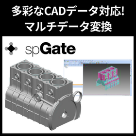
Organizing CAD data into a format that makes it easy to convert to NC data! Utilizing spGate.

Data conversion and modification software that serves as a bridge from CAD to CAM.

To smoothly generate NC data with CAM, the quality and format of the underlying CAD data are extremely important. spGate can be utilized as a data conversion and modification software that bridges CAD and CAM. If the 3D model received from the design department contains issues such as the following, it can lead to problems during the machining stage: - Gaps in surfaces or discontinuous edges - Irregular curvature or distorted surfaces - High-density surfaces with too many control points These issues can cause abnormal behavior or disruptions in the tool path generation in CAM, posing a risk of decreased accuracy of NC data and machining quality. spGate detects these problems in advance and automatically performs healing processes. Furthermore, it can automate conversion and modification processes through batch execution, allowing for efficient processing of multiple CAD data and reducing rework on the shop floor. We have introduced actual cases where the implementation of spGate significantly reduced troubles in NC data creation on the following page. Please take a look.

  • Data conversion software
  • soft

Added to bookmarks

Bookmarks list

Bookmark has been removed

Bookmarks list

You can't add any more bookmarks

By registering as a member, you can increase the number of bookmarks you can save and organize them with labels.

Free membership registration

Processing Path Interval and Surface Roughness - The Relationship Between Roughness Symbols and Path Intervals -

For those who want to confirm the relationship between the precision symbols on the drawings and the processing! An explanation of CAM settings and surface roughness.

In the manufacturing of plastic molds, press molds, forging molds, and casting molds, we will introduce the relationship between surface roughness and the pitch of machining paths when using 3D CAM. We hope this will be somewhat helpful to you. The content we will explain is intended for those who fall into the following categories. Please take a look. 【Recommended for the following people】 ■ Those who want to confirm the relationship between tool radius and surface roughness ■ Those who are unsure about setting the pitch between paths in CAM ■ Those who want to confirm the relationship between precision symbols on drawings and machining *You can view the detailed content of the article through the related links. For more information, please download the PDF or feel free to contact us.

  • 2D CAM
  • 3D CAM
  • Other CAM related software
  • soft

Added to bookmarks

Bookmarks list

Bookmark has been removed

Bookmarks list

You can't add any more bookmarks

By registering as a member, you can increase the number of bookmarks you can save and organize them with labels.

Free membership registration

Overview of the CAD/CAM Integration Programming Tool 'START'

A seamless DesignCAM that integrates the functionality of staying ahead of the times! Experience the effectiveness of an open database.

"START" is a design software that integrates "CAD/CAM," "2D/3D," and "manual/programming," developed and sold since 1991. It is usable in a Windows environment and is equipped with features specialized for the design of various electronic devices, achieving high efficiency in all design tasks from concept to detail. Additionally, it provides an environment that is easy for users to customize, such as through the publication of databases and dedicated programming languages, supporting the development of unique technical know-how. 【Three Major Features】 ■ Fusion of 2D and 3D ■ Fusion of manual operation and programming ■ Fusion of design and editing *For more details, please refer to the PDF materials or feel free to contact us.

  • 2D CAD Electrical
  • soft

Added to bookmarks

Bookmarks list

Bookmark has been removed

Bookmarks list

You can't add any more bookmarks

By registering as a member, you can increase the number of bookmarks you can save and organize them with labels.

Free membership registration

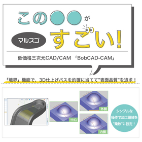
Malsugo: Pursuing surface quality by accurately applying 3D finishing passes with boundary functions.

Creating paths that pursue surface quality! This explains the "Boundary" function of "BobCAD-CAM," which offers overwhelming low prices and comprehensive features.

In finishing processes for shapes that include edges or where curvature changes sharply, unintended paths can be generated in areas not intended, which can affect the finishing quality. In such cases, the "boundary" function for partial specification of the machining area comes into play. Furthermore, the commands for "boundary projection onto surfaces" and "adjustment of tool control points" provide flexibility in this specification. By utilizing these features, you can create arbitrary paths only in the necessary areas! It is possible to apply paths appropriately and pursue the surface quality of finishing processes. The materials also explain the flow of boundary projection and the differences in machining paths due to the adjustment of tool control points, so please take a look. *You can download the materials from the button below.

  • Other CAD related software
  • Other CAM related software
  • 3D CAM
  • soft

Added to bookmarks

Bookmarks list

Bookmark has been removed

Bookmarks list

You can't add any more bookmarks

By registering as a member, you can increase the number of bookmarks you can save and organize them with labels.

Free membership registration

CAD/CAM nesting software 'SigmaNEST'

Maximize the performance of the cutting machine! Manage the entire processing workflow from estimation to production and shipping.

"SigmaNEST" is a nesting software that maximizes productivity through its extensively customizable modular features. It can read parts from any system as long as they are in common CAD formats, automatically categorizing tasks by material and machine, thereby fully utilizing the capabilities of materials and machines to create NC data for your cutting machines. Additionally, it is possible to track the production status from upstream to downstream in the workflow. 【Features】 ■ Improved productivity and efficiency through high-speed cutting ■ Achieved an average material cost reduction of 4% through advanced nesting technology ■ More flexible and simpler operations possible with a single system ■ More accurate planning and operational management through data sharing ■ Strengthened internal teams through high-speed processing and automation *For more details, please refer to the PDF document or feel free to contact us.

  • Other CAD related software
  • Other CAM related software
  • Other CAD
  • soft

Added to bookmarks

Bookmarks list

Bookmark has been removed

Bookmarks list

You can't add any more bookmarks

By registering as a member, you can increase the number of bookmarks you can save and organize them with labels.

Free membership registration

VISI Wire: CAM Software

Reduce human error! Eliminate the need for dry runs in the processing site to cut unnecessary costs.

"VISI Wire" is a cutting-edge product that incorporates wire electrical discharge machining solutions into the VISI CAD/CAM environment developed for tool and mold manufacturing. It is feature-based and automatically recognizes shapes for wire discharge machining, such as tapers and 4-axis machining, directly from solid models, providing reliable machining results. When using 2D data, features for wire discharge machining can be manually created, and machining operations selected from the feature tree can be directly applied. 【Features】 ■ Automatic feature recognition ■ Intuitive user interface ■ Easy feature editing operations ■ Wire discharge machining simulation *For more details, please refer to the PDF document or feel free to contact us.

  • Other CAD related software
  • Other CAM related software
  • Other CAD
  • soft

Added to bookmarks

Bookmarks list

Bookmark has been removed

Bookmarks list

You can't add any more bookmarks

By registering as a member, you can increase the number of bookmarks you can save and organize them with labels.

Free membership registration

Caddit Project Co., Ltd.

Solutions for the design and manufacturing industry.

We offer solutions for the design and manufacturing industry, including CAD, CAM, and CAE. From a wide range of products, we propose the most suitable options and provide consistent support from training to post-implementation assistance. Areas of Expertise: Proposal and implementation support for design and manufacturing solutions such as 2D/3D CAD/CAM/CAE. Proposing and selling optimal solutions to solve customer challenges. Setup and installation during implementation. Support for startup through training and assistance after implementation.

Added to bookmarks

Bookmarks list

Bookmark has been removed

Bookmarks list

You can't add any more bookmarks

By registering as a member, you can increase the number of bookmarks you can save and organize them with labels.

Free membership registration

Troubles during processing: Human error

It can lead to serious troubles that may result in interference incidents... "NCVIEW" allows for efficient verification of troubles!

Even if you create NC data through CAM after modeling in CAD, if there are errors in the data input into the CAD/CAM, you will not obtain correct NC data. Even if the NC data is accurate, mistakes in the NC macro program, incorrect tool compensation settings, or errors in the workpiece's position, orientation, or coordinate system settings can lead to significant problems, such as reduced operational efficiency and quality defects, and in some cases, even interference accidents. By using 'NCVIEW,' which allows simulations in an environment similar to the actual machining setup and has a macro debugger, you can efficiently verify machining troubles. [Causes of Problems] ■ If there are errors in the data input into CAD/CAM, correct NC data cannot be obtained. ■ Mistakes in the NC macro program. ■ Tool compensation settings are not correctly set. ■ Errors in the workpiece's position, orientation, or coordinate system settings. → This can lead to significant problems, such as reduced operational efficiency and quality defects, and in some cases, even interference accidents. *For more details, please refer to the PDF document or feel free to contact us.

Added to bookmarks

Bookmarks list

Bookmark has been removed

Bookmarks list

You can't add any more bookmarks

By registering as a member, you can increase the number of bookmarks you can save and organize them with labels.

Free membership registration

CAD/CAM Integration Customized Software [START]

A development-oriented design tool that can build systems with proprietary technology.

It is equipped with programming capabilities, enabling the creation and editing of data that has no precedent until now. Additionally, by emphasizing user customization through menu customization, layer configuration, and free registration of base libraries, it enhances operability and versatility. It allows for the integration of unique technologies into software, such as the construction of DRC systems, design environment setup, special corrections, fully automated drawing creation, metal mask data creation, and device interfaces. ◆ What is the SeF programming function (START EXECUTE FORMAT)? It is a fully-fledged programming language developed independently, capable of everything from easily creating detection functions at a basic level to advanced editing processes of placement data. It allows for the description of all diverse placement objects using object members, making it a programming language that anyone can create, specifically tailored for wiring design.

  • 2D CAD Electrical
  • 2D CAM
  • Modeler
  • soft

Added to bookmarks

Bookmarks list

Bookmark has been removed

Bookmarks list

You can't add any more bookmarks

By registering as a member, you can increase the number of bookmarks you can save and organize them with labels.

Free membership registration

3D CAD software for manufacturing industry "Creo Parametric"

Integrated platform for CAD/CAM/CAE to enhance design quality.

Creo is a 3D CAD solution that accelerates product innovation and enables the realization of higher quality products in a shorter time frame. Not only is it easy to learn, but its model-based approach seamlessly connects the entire process from the early stages of product design to post-manufacturing. Creo combines proven excellent features with new technologies such as generative design, real-time simulation, advanced manufacturing, industrial IoT, and augmented reality (AR).

  • 3D CAD
  • soft

Added to bookmarks

Bookmarks list

Bookmark has been removed

Bookmarks list

You can't add any more bookmarks

By registering as a member, you can increase the number of bookmarks you can save and organize them with labels.

Free membership registration

VISI mould making: Resin mold software

End-to-end CAD/CAM solutions specialized for the mold design and manufacturing industry!

This catalog introduces 'VISI', an end-to-end solution optimized for mold manufacturing. It supports all aspects of the mold manufacturing process, from model analysis and plastic flow front simulation to core and cavity separation, electrode production, and 3D mold construction. [Contents] ■ Design and manufacturing support CAD/CAM/CAE software ■ VISI Modelling ■ VISI Analysis ■ VISI Electrode ■ VISI Mould ■ VISI Flow *For more details, please refer to the PDF document or feel free to contact us.

  • Other CAD related software
  • Other CAM related software
  • Other CAD
  • soft

Added to bookmarks

Bookmarks list

Bookmark has been removed

Bookmarks list

You can't add any more bookmarks

By registering as a member, you can increase the number of bookmarks you can save and organize them with labels.

Free membership registration

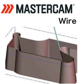
3DCAD/CAM『Mastercam Wire』

Flexibly accommodating cutting patterns from 2D contours to 4-axis vertical irregular shapes.

■Wire (Wire Electrical Discharge Machining) You can flexibly specify cutting patterns from 2D contours to 4-axis upper and lower irregular shapes. It is possible to call up discharge conditions from a library that considers secondary cuts and other factors. You can also insert control codes at any position during tool path editing, as well as verify the machined shape through replotting and verification.

  • mastercam_wire_1.jpg
  • mastercam_wire_2.jpg
  • mastercam_wire_3.jpg
  • 3D CAD
  • 3D CAM
  • Other CAM related software
  • soft

Added to bookmarks

Bookmarks list

Bookmark has been removed

Bookmarks list

You can't add any more bookmarks

By registering as a member, you can increase the number of bookmarks you can save and organize them with labels.

Free membership registration

CAM solution "High-speed surface machining"

High-speed surface machining of partial surfaces – An essential module for all processing sites!

SolidCAM's high-speed surface machining is a high-speed surface machining module that smoothly and powerfully processes curved surfaces in partial areas of parts, including undercuts. You can easily select the surfaces to be machined without defining the area. It supports standard and shaped tools. 【Features】 ○ Powerful surface machining with smooth and interference-free optimal tool paths ○ Complete tool control that processes only the selected areas ○ Advanced interference control for holders, arbors, and tools ○ Advanced linking ○ An essential module for all machining environments For more details, please contact us or download the catalog.

  • Other CAM related software
  • soft

Added to bookmarks

Bookmarks list

Bookmark has been removed

Bookmarks list

You can't add any more bookmarks

By registering as a member, you can increase the number of bookmarks you can save and organize them with labels.

Free membership registration

March 26 (Tuesday) 3D CAD Seminar for Designers

TopSolid" eliminates hassle with complete integration of 2D and 3D CAD. We will hold a seminar on "3D Efficiency without Rework.

CAD/CAM is a management tool that brings significant results to overall management. ■ Would you like to reduce design man-hours? ■ Are you able to link data both within and outside your department? ■ Are you able to accumulate and utilize the design know-how you have developed? ■ Are you spending too much time on corrections and creating assembly and part drawings during design changes? ---------------- Choosing CAD/CAM can sometimes lead to increased learning efforts and implementation costs, rather than improving productivity. 3D CAD/CAM does not change the system on its own. It is essential to thoroughly restructure the efficient workflow and job structure in line with 3D implementation before introducing the system that can maximize productivity. Your common sense may become the catalyst for change. Please join our free seminar.

Added to bookmarks

Bookmarks list

Bookmark has been removed

Bookmarks list

You can't add any more bookmarks

By registering as a member, you can increase the number of bookmarks you can save and organize them with labels.

Free membership registration

3D CAD/CAM/CAE system 'CATIA V5'

Achieve excellent product design with 3D CAD! Capable of supporting various manufacturing industries and a wide range of sectors.

"CATIA V5" is a 3D CAD/CAM/CAE system that is widely used by many customers around the world, covering mid-range to high-end applications. It can accommodate a variety of manufacturing industries, from OEMs to supply chains, including automotive, aerospace, electrical and electronics, industrial machinery, and consumer goods. The excellent features and usability of this product allow for the easy representation of complex shapes that were not possible with traditional 2D CAD. [Features] - Widely used in the fields of engineering and design around the world - Achieves superior product design through 3D CAD - Supports various companies involved in manufacturing, from OEMs to supply chains and small-scale individual manufacturers *For more details, please refer to the PDF document or feel free to contact us.

Added to bookmarks

Bookmarks list

Bookmark has been removed

Bookmarks list

You can't add any more bookmarks

By registering as a member, you can increase the number of bookmarks you can save and organize them with labels.

Free membership registration

Eureka Chronos: NC Optimization Software

A simulation tool equipped with AI that optimizes sending speed with easy operation.

【Eureka Chronos Features】 The artificial intelligence (AI: Artificial Intelligence) algorithm (patented by Roboris Sir) automatically adjusts the feed rate based on the actual cutting tool conditions, maintaining the amount of material removed (VR) as constant as possible over time, enabling the optimization of cutting processes. It is possible to achieve a reduction in processing time of over 30% compared to conventional cutting processing times.

  • simulator
  • soft

Added to bookmarks

Bookmarks list

Bookmark has been removed

Bookmarks list

You can't add any more bookmarks

By registering as a member, you can increase the number of bookmarks you can save and organize them with labels.

Free membership registration

Problem-Solving Materials: Improving Operating Rate Edition 2 | Program Creation Time (1)

Solving the decrease in equipment utilization rate caused by the creation of processing programs! A document for discovering and solving issues in the production site.

Amid the demand for short delivery times and a wide variety of products, the importance of "improving operational efficiency" is increasing. This document is a series that proposes various solutions to the challenges faced by production sites, focusing on the theme of "improving operational efficiency," from identifying issues to finding solutions. In Vol. 2, we will introduce the causes and solutions for "decreased operational efficiency due to program creation." [Document Overview] The division of labor between program creation and machine operation is effective in addressing the decrease in operational efficiency caused by manual and interactive program creation. By utilizing CAD/CAM to create programs in advance, various benefits can be gained in addition to improving operational efficiency. However, there are various challenges to starting the operation of CAD/CAM. This document will focus on solutions to the challenges of "human resource development" and "program creation time." *You can download the document using the button below.

  • Production Management System
  • 2D CAM
  • 3D CAM
  • soft

Added to bookmarks

Bookmarks list

Bookmark has been removed

Bookmarks list

You can't add any more bookmarks

By registering as a member, you can increase the number of bookmarks you can save and organize them with labels.

Free membership registration

I tried creating my own document template for Mitarépo.

[Mitarepo] Efficiently prepare before processing settings! I tried creating a template that matches the stock size! | System Create

Mitarepo is a series that introduces what can be done using various products, based on the concept of "Trying Out This Kind of Thing!" We deliver useful information each time from the wide range of product genres handled by System Create. BobCAD-CAM can be introduced and operated at a low cost. Despite its overwhelmingly low price, it is well-received because it combines a variety of modules with rich features. One of its features is the ability to set up the environment according to stock sizes! When performing router processing, using standard-sized materials reduces the effort required for material cutting and preparation on the processing site, allowing for efficient work. When using CAM, wouldn't it be great to start creating processing steps immediately if there were formats tailored to stock sizes? This time, we created a document template tailored to standard sizes using BobCAD-CAM! In the materials, we explain how to set the stock size and processing origin, along with the creation methods and images, detailing how many steps are involved in the setup. *You can download the materials from the button below.

  • 3D CAD
  • 3D CAM
  • Other CAD related software
  • soft

Added to bookmarks

Bookmarks list

Bookmark has been removed

Bookmarks list

You can't add any more bookmarks

By registering as a member, you can increase the number of bookmarks you can save and organize them with labels.

Free membership registration

WIRE CAM DX Introduction Case Study <Dainichi Seisakusho Co., Ltd.>

Even unskilled workers can become immediately productive! Achieving efficiency in board manufacturing!

We would like to introduce how the introduction of "WIRE CAM DX" has addressed the strong sense of crisis regarding the aging of wiring workers at Daiichi Seisakusho Co., Ltd., which broadly engages in equipment design and system design, centered on the manufacturing of distribution boards, control panels, and sub-distribution boards. ■ Background of Introduction - A strong sense of crisis regarding the aging of wiring workers - Creating a system where anyone can manufacture products with the same quality - Simultaneously aiming for standardization ■ Reasons for Adopting WIRE CAM DX - Adopted WIRE CAM DX, which allows for wiring length measurement not only from ECAD DCX drawings but also from AutoCAD drawings, enabling manufacturing and data linkage. ■ Effects After Introduction - Approximately 15% reduction in overall man-hours from design to manufacturing within about a year and a half after introduction. - Changed to wiring design based on standardized rules by digitizing wiring routes and know-how. - After about six months of training post-implementation, individuals can independently view drawings and perform wiring tasks. - Data linkage to wire processing machines has mechanized manual tasks, reducing work hours and improving quality. - Overall quality level of products has also improved.

Added to bookmarks

Bookmarks list

Bookmark has been removed

Bookmarks list

You can't add any more bookmarks

By registering as a member, you can increase the number of bookmarks you can save and organize them with labels.

Free membership registration