
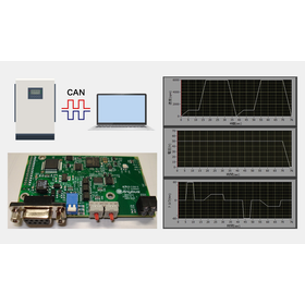
Achieved the elimination of double operation and automation of testing through inverter CAN communication control.
The company introducing this case study is a manufacturer developing drive units for electric vehicles in Japan. They are engaged in the development and evaluation of motors and inverters for EVs, and there was a demand for advanced performance verification using dynamometer testing machines. Within this context, there was a request to link the inverter, which is the test specimen, with the testing machine, sending command values from the testing machine side via CAN communication for integrated control. In the evaluation field for motors and inverters for electric vehicles, speed or torque was input from the testing machine side, and load tests for the inverter and motor were conducted. However, in the conventional testing environment, it was necessary to operate the inverter on the test specimen side and the testing machine side using separate PCs, leading to the complexity of setting, starting, and monitoring individually. It was burdensome for the site to have to operate two PCs back and forth for each test. At SeaGoTo Co., Ltd., in order to integrate the control systems that were separated between the testing machine side and the test specimen side for load testing of motors and inverters for electric vehicles, a modification of the control system utilizing CAN communication was implemented.
Inquire About This Product
basic information
In this system, the test condition data sent from the PC is processed by an embedded CPU, and the output is converted into data formats suitable for each communication specification: EtherCAT for the inverter on the test machine side and CAN communication for the inverter on the specimen side. Control is executed in a loop processing structure with a cycle time in milliseconds, sending command values to each inverter on the same time axis. This eliminates the temporal discrepancies that occurred due to manual operations, enabling high-precision synchronization of the movements between the test machine and the specimen. Additionally, torque commands to the specimen inverter and speed control on the test machine side are all processed within the same control loop, allowing for automated testing such as pattern operation. This system consolidates the control and monitoring functions for the inverters on both the test machine and specimen sides into a single PC screen, significantly improving operability. Furthermore, abnormal information acquired from the specimen inverter is monitored by the embedded CPU, and in the event of an anomaly, synchronized stop commands are output to both the test machine side and the specimen side. This eliminates the risk of one side stopping while the other continues to operate, as was the case in the past.
Price range
Delivery Time
Applications/Examples of results
The introduction of this system has enabled integrated control of the testing machine and the specimen inverter, significantly improving the efficiency and quality of testing operations. By controlling speed and torque on the same time axis, pattern operation and long-duration continuous testing have become possible, enhancing automation and reproducibility of tests. The reliability of evaluation data has also increased. Additionally, in the event of an anomaly, both systems stop synchronously, reducing the risk of damage to equipment and specimens due to overspeed or overload, greatly improving safety. Furthermore, the need for operation and communication environment setup with multiple PCs has been eliminated, reducing the preparation and operational workload for testing. The improvement in testing efficiency and reduction in troubles have also led to shortened development periods and cost savings.
Detailed information
-
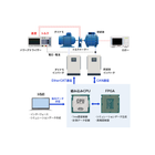
At C-GOAT, we implemented modifications to the control system utilizing CAN communication to integrate the control systems that were previously separated between the test equipment side and the specimen side during load testing of motors and inverters for electric vehicles. In this system, a CAN communication module was added to the test equipment side, allowing for the transmission of command values to the specimen inverter via CAN communication, in addition to the conventional EtherCAT control of the test equipment inverter, all within the same control system. This enables unified control of both sides, which were previously configured with different communication protocols, creating a synchronized testing environment. The system processes the test condition data sent from a PC using an embedded CPU, converting and outputting the data into formats suitable for each communication specification: EtherCAT for the test equipment side inverter and CAN communication for the specimen side inverter. Control is executed in a loop processing structure with a cycle in milliseconds, sending command values to each inverter on the same time axis. This eliminates the temporal discrepancies that occurred with manual operations, allowing for high-precision synchronization of the operations between the test equipment and the specimen.
Company information

Our company is engaged in measurement and control applications, test simulation proposals, replacement and functional enhancement of test equipment and measurement, and the provision of original hardware. With the mission of "making the world simpler and better" through software and electronics technology, we create value through technological development and will continue to contribute sustainably to various industrial fields. Please feel free to contact us when you need our services.
![[For New Graduates and Young Engineers] Communication and Control with PLCs](https://image.mono.ipros.com/public/product/image/d60/2000474136/IPROS24215151538865713293.jpeg?w=280&h=280)