We have compiled a list of manufacturers, distributors, product information, reference prices, and rankings for CAD.
ipros is IPROS GMS IPROS One of the largest technical database sites in Japan that collects information on.

CAD Product List and Ranking from 150 Manufacturers, Suppliers and Companies | IPROS GMS

Last Updated: Aggregation Period:Jul 15, 2026~Aug 11, 2026
This ranking is based on the number of page views on our site.

CAD Manufacturer, Suppliers and Company Rankings

Last Updated: Aggregation Period:Jul 15, 2026~Aug 11, 2026
This ranking is based on the number of page views on our site.

  1. iCAD - 機械設計向け3DCAD(3次元CAD)開発元 - Tokyo//CAD/CAM
  2. ECAD Solutions Co., Ltd. Saitama//CAD/CAM
  3. マーブル  エンベデッドプロダクト事業本部 プロダクト事業部 Tokyo//IT/Telecommunications
  4. 4 Design Creation Inc. Tokyo//software
  5. 5 進和電機 Aichi//Consumer Electronics

CAD Product ranking

Last Updated: Aggregation Period:Jul 15, 2026~Aug 11, 2026
This ranking is based on the number of page views on our site.

  1. Electrical design CAD 'Unidraf X / Unidraf G' 進和電機
  2. Mastering 2D! 【 MICRO CADAM Helix 】 CAD SOLUTIONS 本社
  3. 2D3D Integrated CAD CADPAC-CREATOR [Free Trial Version] Design Creation Inc.
  4. 4 Electric CAD "Tried ECAD DCX!" 1 ECAD Solutions Co., Ltd.
  5. 5 3D CAD for Aluminum Products 'apdX' SUS

CAD Product List

301~330 item / All 552 items

Displayed results

Electrical design CAD 'IJCAD Electrical'

Equipped with a statistical database! Achieves integration with circuit diagrams and various documents.

"IJCAD Electrical" is an electrical design CAD that comes standard with the functions necessary for control panel and distribution board design. With the integration of a database, documents such as circuit diagrams and parts lists are seamlessly linked. The previously cumbersome design change process is significantly streamlined, allowing for the creation of high-quality drawings. 【Features】 ■ Based on the industry standard .dwg, it can handle AutoCAD data ■ Enables drawing integration through an integrated database not found in typical drafting CAD ■ Low cost ■ Seamless linking of circuit diagrams, parts lists, terminal block tables, and other documents due to the database integration ■ Design change processes are greatly streamlined, enabling the creation of high-quality drawings *For more details, please refer to the PDF materials or feel free to contact us.

Added to bookmarks

Bookmarks list

Bookmark has been removed

Bookmarks list

You can't add any more bookmarks

By registering as a member, you can increase the number of bookmarks you can save and organize them with labels.

Free membership registration

For Electrical Designers: CAD 'IJCAD Electrical'

Supporting the realization of efficiency! A full-fledged electrical design CAD equipped with essential features for board design as standard.

"IJCAD Electrical" is a full-fledged electrical design CAD that comes standard with essential features for electrical design, such as "page management," "symbols," "wire numbering," "reference management," and "report creation." Not only can you perform circuit design with simple operations, but various error-checking functions also prevent omissions and duplications of device numbers and wire numbers, which often lead to rework, allowing for the quick creation of high-quality drawings. The wiring function allows for wiring that matches the design content, including standard wiring and angled wiring, and for multi-phase wiring, it is easy to create drawings for 2-phase to 4-phase wiring. 【Features】 ■ Industry-standard .dwg-based, allowing for handling AutoCAD data ■ Excellent operability ・Significantly reduces startup time ■ Overwhelmingly low price *For more details, please refer to the PDF materials or feel free to contact us.

  • Other CAD
  • Data conversion software
  • CAD

Added to bookmarks

Bookmarks list

Bookmark has been removed

Bookmarks list

You can't add any more bookmarks

By registering as a member, you can increase the number of bookmarks you can save and organize them with labels.

Free membership registration

IHI Corporation [iCAD] 3D CAD Implementation Case Study

Reduce design time for large industrial machinery by 30%! Significant reduction in rework through business reform using 3D CAD!

We would like to introduce a case study of business improvement using the 3D CAD "iCAD SX," which is specialized in mechanical design. IHI Corporation was using 2D CAD for the design of large industrial machinery, but the 2D drawings could only be understood by the designers, leading to a constant struggle with meetings and document preparation for various stakeholders. In order to improve the increasingly burdensome working environment for designers, they decided to transition to 3D design. After searching for a 3D CAD that could flexibly respond to customer needs, they selected "iCAD SX." As a result, they successfully built a design environment that minimizes design rework to the utmost by early disclosure of design information through 3D models and enhancing design reviews with customers and internal related departments. [Main Effects of Implementation] - Enhanced design reviews (DR) with customers and stakeholders, leading to reduced rework. - Successful improvement of work efficiency in piping design, which was difficult with 2D. - Achieved a 30% reduction in design time compared to what was estimated with 2D CAD. [Download Materials] - Currently available for limited viewing on the special site. Please click the link below.    ▼▼▼ Click here ▼▼▼

Added to bookmarks

Bookmarks list

Bookmark has been removed

Bookmarks list

You can't add any more bookmarks

By registering as a member, you can increase the number of bookmarks you can save and organize them with labels.

Free membership registration

DENSO Co., Ltd. [3D CAD Implementation Case] i CAD SX

Designing over 100 production facilities with 3D CAD! Designing and manufacturing specialized machines filled with unique technology without any setbacks!

We would like to introduce a case study of business improvement using the specialized 3D CAD "iCAD SX" for mechanical design. At Denso Corporation, they are internalizing the production equipment for automotive parts. As the equipment became more complex and large-scale, they felt the limitations of 2D inspection through visual checks and decided to transition to 3D design. After acquiring high-end CAD and several mid-range CAD systems, they conducted actual design and benchmarking, ultimately selecting "iCAD SX" as it could handle the assembly of processing machines with over 10,000 parts. As a result, after a trial introduction period, it was officially adopted as the standard 3D CAD for the entire company. They have achieved "no return" by designing over 100 production facilities in 3D. [Main Effects of Implementation] - Labor-saving from detailed drawing design to assembly and design stages - Improvement in design quality, cost reduction, and enhanced competitiveness - High-precision simulation of equipment, robots, and human movements [Download Materials] - Currently available for limited access on the special site. Please click the link below.    ▼▼▼ Click here ▼▼▼

Added to bookmarks

Bookmarks list

Bookmark has been removed

Bookmarks list

You can't add any more bookmarks

By registering as a member, you can increase the number of bookmarks you can save and organize them with labels.

Free membership registration

Presentation of case studies. What is the 3D CAD required for the design of material handling and transportation equipment?

3D CAD that achieves a reduction in lead time for transportation equipment development! Realizing ultra-fast response capable of handling 3 million parts in 0.2 seconds.

In the design of conveying equipment, the requirements vary for each customer due to factors such as the conveyed items and factory layout, necessitating a unique and quick turnaround design for each case. To achieve a vertical startup of the equipment, it is crucial to extract detailed customer requirements at an early stage of specification discussions and to help them quickly understand the structure and operability of the equipment. For mechanical designers, the 3D CAD iCAD SX achieves high-speed response, handling 3 million parts in 0.2 seconds. You can manage the entire conveying equipment, including material handling devices like conveyors and AGVs, on 3D CAD without stress. Since the movements of the machinery can be simulated in advance for the entire system, there is no worry about damaging the machinery or causing harm to people. This leads to improved design quality and reduced development lead times. \\Customer case studies that have realized manufacturing DX are exclusively available on the 【special site】/ /                     ^^^^^^^^^^^^^ ▶ Click on the special site to download the case studies now!  ↓↓↓

Added to bookmarks

Bookmarks list

Bookmark has been removed

Bookmarks list

You can't add any more bookmarks

By registering as a member, you can increase the number of bookmarks you can save and organize them with labels.

Free membership registration

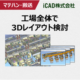
[Case Presentation] Reduced design time by 30%! 3D CAD suitable for plant design.

Revolutionizing design operations with 3DCAD has drastically reduced design rework! Achieving ultra-fast responses for piping considerations across the entire factory.

In plant design, it is necessary to consider the space for piping routes, workability, and maintainability based on the customer's industry, factory layout, and other factors. Therefore, a unique and short-term design is required. To meet the high demands of customers, it is important to conduct preliminary verification of the entire plant, including surrounding equipment and work areas, rather than just focusing on the piping alone. This helps to reduce rework that may occur during the on-site startup. iCAD SX achieves high-speed response, handling 3 million parts in 0.2 seconds. Not only can you manage mechanical equipment, but you can also handle the entire factory, including plant piping, on 3D CAD without stress. Since you can consider the space for piping routes, workability, and maintainability during the design phase, it allows for the identification and resolution of issues and mistakes during the review process. Additionally, by conducting specification meetings using a three-dimensional model, you can improve communication with customers. This leads to enhanced design quality and reduced development lead times. ◎ Customer case studies are currently available for limited viewing on a special site! ▶ Click on the special site and download now!   ↓↓↓

Added to bookmarks

Bookmarks list

Bookmark has been removed

Bookmarks list

You can't add any more bookmarks

By registering as a member, you can increase the number of bookmarks you can save and organize them with labels.

Free membership registration

A must-see for mechanical designers! What 3D CAD is required for mechanical equipment development?

3D CAD specialized in mechanical design! Achieve 3D business transformation with "super-fast response" and "intuitive operability."

In mechanical device design, business reform utilizing 3D data has been advocated for over 10 years. However, there are often voices expressing that even with the introduction of 3D CAD, the effects are not realized, and that 3D design itself is not being adequately performed. To achieve results with 3D CAD, it is essential to implement a 3D CAD system that is suitable for the mechanical design process. Fujitsu's design and manufacturing support iCAD SX is a domestically developed 3D CAD specifically designed to support manufacturing in Japan. iCAD achieves high-speed response capable of handling 3 million parts in 0.2 seconds, allowing for stress-free design consideration and verification of entire devices comprising tens of thousands of components. Moreover, during the conceptual phase where various ideas are materialized and trial and error occurs, users can create 3D models without being constrained by history or constraints, much like sketching a rough drawing. The created models can be freely edited later and gradually detailed, enabling 3D design to be realized through the same design process as 2D design. Customer case studies are currently available for limited viewing on a special site. Please click on "▶Special Site" to check it out.

Added to bookmarks

Bookmarks list

Bookmark has been removed

Bookmarks list

You can't add any more bookmarks

By registering as a member, you can increase the number of bookmarks you can save and organize them with labels.

Free membership registration

What is 3D CAD that realizes shorter delivery times and higher quality for machine tools and processing machines?

Reduce rework in the later stages! 3D CAD that can detect and correct issues during the design phase.

Currently, in the market for machine tools and processing machines, there is an increasing demand for high-quality products with short delivery times. Instead of repeatedly prototyping to ensure quality, it is important to identify and correct issues during the design phase to reduce rework. iCAD achieves high-speed response capable of handling 3 million parts in 0.2 seconds. Even with large machine tools, it can manage the entire assembly on 3D CAD, allowing for the accumulation and utilization of various information, including movement and electrical/control data. For example, confirming movements using device models and utilizing electrical circuit diagrams for automatic wiring routing make it possible to conduct considerations that were previously done on actual machines during the design phase. This prevents damage to actual machines due to dynamic interference and increases in man-hours due to on-site wiring path adjustments, enabling the production of high-quality machines with short delivery times. \ Customer case studies are exclusively available on the <Special Site>! /  ▶ Click on the Special Site and download now!   ↓↓↓

Added to bookmarks

Bookmarks list

Bookmark has been removed

Bookmarks list

You can't add any more bookmarks

By registering as a member, you can increase the number of bookmarks you can save and organize them with labels.

Free membership registration

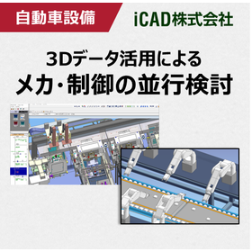
Realizing parallel examination of mechanics and control! 3D CAD suitable for automotive equipment design.

Achieving front-loading in automotive equipment development, including control and robot verification! Ultra-fast response 3D CAD that smoothly handles large-scale data.

In the automotive industry, there is a demand for the rapid market introduction of new vehicles, which requires the development of automotive production equipment with short delivery times and high quality. Additionally, not only mechanical design but also PLC simulation of equipment and welding robot simulation are becoming more complex, leading to the use of simulators for pre-validation. However, general simulation software requires the conversion of 3D CAD data, necessitating the reconfiguration of mechanisms and IO information with each design change. This makes it difficult to conduct parallel considerations in line with design progress, and many customers may have given up on this approach. To solve this issue, it is important to achieve control debugging and robot simulation directly on the 3D CAD platform. iCAD SX offers ultra-fast response by processing 3 million parts in 0.2 seconds, allowing it to handle vast amounts of data, including the operation and control information of large-scale models, and enables control debugging and robot simulation directly on the 3D CAD. This facilitates an earlier start to control design, shortening the equipment development period and achieving front-loading. ▶ A special site is currently showcasing limited case studies!    ↓↓↓

Added to bookmarks

Bookmarks list

Bookmark has been removed

Bookmarks list

You can't add any more bookmarks

By registering as a member, you can increase the number of bookmarks you can save and organize them with labels.

Free membership registration

Piping and wiring design

Large-scale routing on 3D CAD assemblies! Significant reduction in rework labor at the manufacturing site through prior wiring considerations.

In mechanical devices and production/plant equipment, it is important to be able to consider not only the mechanics but also the piping, wiring, and steel materials while confirming the surrounding arrangements. However, the following issues arise at the design site. 【Common Concerns】 - The 3D CAD data is heavy, making it difficult to consider piping and wiring. - Since piping and wiring are designed using specialized software, any modifications on the mechanical side require restarting the 3D CAD each time. - Using multiple software makes it difficult to maintain consistency. - Design reviews are conducted with a viewer, so modifications cannot be made on the spot. All of the above issues can be resolved. With COLMINA Design and Manufacturing Support iCAD SX (hereinafter referred to as iCAD), we have achieved a processing performance of 0.2 seconds for 3 million parts through the incorporation of proprietary technology. We have succeeded in reducing the weight of 3D data to about 1/50 of its original weight (compared to our company), and by accumulating and utilizing all information on large-scale piping, wiring, and steel materials in iCAD, we support the realization of manufacturing DX. For details, please download the catalog and check it.

Added to bookmarks

Bookmarks list

Bookmark has been removed

Bookmarks list

You can't add any more bookmarks

By registering as a member, you can increase the number of bookmarks you can save and organize them with labels.

Free membership registration

Presentation of Technical Data: Utilization of 3D Data in the Assembly Stage

Introducing the challenges and solutions for utilizing 3D CAD data in assembly, along with the 3D CAD specialized for mechanical design, iCAD SX.

Click the black button [Download Catalog] to get it now. While 3D CAD and 3D design are gradually becoming more widespread, many companies find it difficult to imagine how to utilize 3D in the assembly stage. This document is supervised by the developer of the mechanical design-oriented 3D CAD "iCAD SX." It explains the benefits and specific methods of seamlessly utilizing 3D data from design to assembly, accompanied by diagrams. 【Do you have any of these concerns?】 ◆ The creation of 2D assembly drawings is a burden for designers. ◆ The necessity of design reviews (DR) from an assembly perspective. ◆ Dependence on veteran engineers. → We will introduce solutions to the above issues. Please click "▶ [No registration required for Ipros members] Download case studies here" to check it out.

Added to bookmarks

Bookmarks list

Bookmark has been removed

Bookmarks list

You can't add any more bookmarks

By registering as a member, you can increase the number of bookmarks you can save and organize them with labels.

Free membership registration

High functionality and low price! Circuit diagram/PCB design tool "Quadcept"

Next-generation cloud-based electronic CAD system Quadcept, which integrates EDA solutions and the cloud.

Quadcept Inc. is on a mission to gather the voices of users around the world in the EDA industry, prioritize their wishes, and provide a cloud-based electronic CAD that grows together with our customers. Based on feedback from many designers, we developed Quadcept. Quadcept offers a high-performance schematic editor and PCB design CAD with no initial costs. It is an innovative CAD software that continues to evolve based on user feedback. Customization is easy, and we provide real-time support through an open user forum. Additionally, to continuously achieve corporate innovation within the development environment, we swiftly absorb customer requests and provide the highest quality service to meet our customers' business needs through rapid deployment of solutions.

  • Company:Quadcept
  • Price:Less than 10,000 yen
  • Other CAD
  • others
  • CAD

Added to bookmarks

Bookmarks list

Bookmark has been removed

Bookmarks list

You can't add any more bookmarks

By registering as a member, you can increase the number of bookmarks you can save and organize them with labels.

Free membership registration

Electrical design CAD 'Unidraf X / Unidraf G'

Various information is processed automatically! A new appeal of CAD for electrical design built over more than 40 years!

"Unidraf" is a CAD software for electrical design. Unlike regular general-purpose CAD, where various information must be manually entered, it automatically processes this information, allowing for the easy creation of high-value electrical drawings without much effort. Furthermore, by creating in a new data format, "symbols and formats on the drawings are embedded on each page," making data management and transfer easier. Unidraf also offers an English version and supports Unicode, which can express languages from around the world. Additionally, it allows for bulk replacement of languages within the drawings to the desired language, enabling design staff to use it without stress. ◆ Drawing Creation and Management You can centrally manage up to 9,999 pages within a single file, covering a single subject sufficiently, from circuit diagrams of hardware and software to panel and outline drawings. ◆ Drawing Search You can efficiently search through a large number of drawing files not only by file name but also based on detailed information contained within the drawings. Other features are also available. For more details, please refer to the PDF materials or feel free to contact us.

  • 2D CAD Electrical
  • CAD

Added to bookmarks

Bookmarks list

Bookmark has been removed

Bookmarks list

You can't add any more bookmarks

By registering as a member, you can increase the number of bookmarks you can save and organize them with labels.

Free membership registration

CAD system "hyperCAD-S"

A CAD basic module suitable for the starting point. Handling geometric elements is very easy even in the subsequent CAM operations.

"hyperCAD-S" is a CAD software that fully utilizes the capabilities of hardware systems to create digital processing data. The advanced ultra-high-performance 64-bit system is a perfect solution that can correctly handle many issues that arise daily in the process of creating precise products and parts by manipulating meshes, faces, and solids. Additionally, it can prepare large amounts of imported data quickly, easily, and safely for later NC programming, and this processing can be executed without relying on the original CAD system at all. 【Features】 ■ Customizable filter functions ■ Intelligent geometric element management ■ Smooth data transfer ■ Intuitive operability ■ Support for all languages *For more details, please refer to the PDF materials or feel free to contact us.

Added to bookmarks

Bookmarks list

Bookmark has been removed

Bookmarks list

You can't add any more bookmarks

By registering as a member, you can increase the number of bookmarks you can save and organize them with labels.

Free membership registration

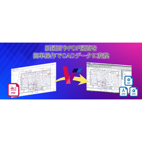
CAD Conversion System VectorMaster

A must-see for those who have given up on reusing PDF drawing data!! Instantly convert PDF drawing data to CAD data!!

VectorMaster is a revolutionary PDF drawing CAD conversion system that restores PDF drawing data, which could not be reused in CAD until now, back to raw CAD data, allowing for editing and processing. The operation is extremely simple! Just select and open the PDF drawing you want to convert to CAD data, and you're good to go! If you've given up on reusing PDF drawings, be sure to take this opportunity to try VectorMaster.

  • Data conversion software
  • Other CAD
  • CAD

Added to bookmarks

Bookmarks list

Bookmark has been removed

Bookmarks list

You can't add any more bookmarks

By registering as a member, you can increase the number of bookmarks you can save and organize them with labels.

Free membership registration

Water Supply and Drainage Application CAD System "Mizushou NX Application"

AI reduces the effort of creating drawings. Make application processes smoother!

The Water Master NX application is a CAD system specialized for plumbing work. Aiming to enable those without specialized knowledge to complete drawings, it offers an automatic drawing function for water supply and drainage application diagrams utilizing AI. Furthermore, by integrating with the ANDES Cloud, which includes features such as project management and estimate management, it streamlines business processes and can be used as a total business support solution for plumbing work.

  • 2D CAD Construction
  • Other CAD
  • CAD

Added to bookmarks

Bookmarks list

Bookmark has been removed

Bookmarks list

You can't add any more bookmarks

By registering as a member, you can increase the number of bookmarks you can save and organize them with labels.

Free membership registration

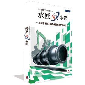
CAD system for water supply main construction "Suishou NX Main Pipe"

It is a CAD system for water supply main construction that allows for easy creation of pipe layout diagrams and daily reports.

The Water Master NX main pipe is a CAD system designed to streamline various drawing creation tasks related to water supply main pipe construction. It incorporates a wealth of unique know-how developed over many years of waterworks and CAD development for water supply main pipe construction, allowing for the quick completion of documents, drawings, daily reports, and more related to water supply main pipe work. By using automated functions, even those without knowledge of main pipe drawings can easily finish the drawings. Additionally, it can be used in various scenarios, such as for road occupation permit applications required during construction, drawings and cross-sections for piping from the main pipe to residences, calculations for road pavement area, and support for electronic submissions (SXF format input/output). 【Features】 ○ CAD system specialized for water supply main pipe construction tasks ○ Streamlines design tasks for water supply main pipe construction ○ Enhances efficiency in creating daily construction reports and pipe allocation drawings ○ Improves efficiency in creating cross-sections and area diagrams ○ Streamlines material usage aggregation and report creation For more details, please contact us.

  • 2D CAD Construction
  • Other CAD
  • CAD

Added to bookmarks

Bookmarks list

Bookmark has been removed

Bookmarks list

You can't add any more bookmarks

By registering as a member, you can increase the number of bookmarks you can save and organize them with labels.

Free membership registration

IJCAD Arch

Equipped with symbols for scenery, sanitary facilities, kitchen equipment, furniture, and fixtures!

"IJCAD Arch" is a CAD software for architectural design that includes the necessary functions for basic design, detailed design, construction drawings, and full-scale drawings. It supports the reading and saving of DWG, DXF, and JWW files. It also features a conversion function that reduces data discrepancies that can be a bottleneck during data exchange between different file formats. Layer control is categorized and designed specifically for architectural and equipment drawings. 【Features】 ■ Supports industry-standard .dwg and .jww files ■ Easy data organization with layer control ■ Creation of quantity and area tables ■ Includes various architectural symbols ■ Capable of architectural drafting ■ Can extract wiring and piping lengths even in 2D drafting *For more details, please download the PDF or feel free to contact us.

Added to bookmarks

Bookmarks list

Bookmark has been removed

Bookmarks list

You can't add any more bookmarks

By registering as a member, you can increase the number of bookmarks you can save and organize them with labels.

Free membership registration

Introduction to the Engineering Division of Japan System Eight Co., Ltd.

Leave the development of automatic inspection devices and clinical testing systems to us.

At Japan System Eight Co., Ltd.'s Engineering Division, we mainly engage in the development of automatic control devices using PC and microcontroller control, as well as the design and production of various dedicated boards. We possess various operating systems such as Windows Server and Linux, and support development languages including C language and Visual Studio 2005 (C++, C#). 【Business Activities】 ■ Development of automatic control devices using PC and microcontroller control ■ Design and production of various dedicated boards ■ Design and development of various dedicated applications, database and network construction *For more details, please refer to our catalog or feel free to contact us.

  • Other contract manufacturing
  • Other contract services
  • CAD

Added to bookmarks

Bookmarks list

Bookmark has been removed

Bookmarks list

You can't add any more bookmarks

By registering as a member, you can increase the number of bookmarks you can save and organize them with labels.

Free membership registration

Precast BIM Software Tekla Structures

Structural BIM software 'Tekla Structures' achieves productivity improvement and cost reduction through detailed structural calculations.

"Tekla Structures" allows for the construction of 3D models of precast concrete structures and enables the management of various information related to manufacturing and construction on a BIM model. By creating 3D models of concrete and rebar components, it can be utilized from basic design to structural calculations, detailed design, site construction, and management, achieving improvements in productivity and cost reduction. In the 3D model, it is possible to check in advance the intersections between rebars, the interference between rebars and steel frames, and the interference with equipment, thereby eliminating issues on site. The placement, joints, and anchoring of rebars can be automatically generated simply by specifying the parameters of the provided components, allowing for accurate tracking of material quantities. From the model, necessary drawings and documentation for manufacturing and construction, such as axis diagrams, rebar detail drawings, and rebar processing drawings, are automatically generated, enabling quick responses to design changes and avoiding inconsistencies between design information and manufacturing drawings. (If the PDF button is not displayed) ⇩ The catalog can be downloaded from the special site below ⇩

  • 3D CAD
  • 2D CAD Construction
  • antenna
  • CAD

Added to bookmarks

Bookmarks list

Bookmark has been removed

Bookmarks list

You can't add any more bookmarks

By registering as a member, you can increase the number of bookmarks you can save and organize them with labels.

Free membership registration

[BIM Software Implementation Case Study] Stadium Renovation Project

Transmitting vertical loads to two linked pendulums! Introducing a case where circulation within the stadium has improved!

We would like to introduce a case study on the introduction of BIM software for the Santiago Bernabéu Stadium renovation project. The new fixed roof, which uses over 9,000 tons of steel, consists of two trusses spanning 177 meters in length and four cross trusses measuring 144 meters in length. This roof is retractable and splits into two panels that slide over the inner cross trusses. The panels are made up of five air-inflatable cushions measuring 72×7 meters, positioned between six steel hybrid trusses with a span of 72.5 meters. Additionally, during the assembly process, the main truss, which served as a guide for the other trusses, transmits vertical loads to two new evacuation towers on the west side and two linked pendulums integrated into the building on the east side, while completely isolating horizontal loads from the existing structure. The redevelopment of the stadium also includes the installation of a video scoreboard. *For more details, please refer to the PDF materials or feel free to contact us. (If the PDF button is not displayed) ⇩ The catalog can be downloaded from the special site below ⇩

Added to bookmarks

Bookmarks list

Bookmark has been removed

Bookmarks list

You can't add any more bookmarks

By registering as a member, you can increase the number of bookmarks you can save and organize them with labels.

Free membership registration

[BIM Software Implementation Case Study] Offshore Platform

We will introduce a case where the use of advanced tools successfully achieved an efficient design process!

The "Azeri Central East (ACE) Project" has become the second largest and most important project for AZFEN. By utilizing advanced tools of Tekla software, such as custom components (streamlining customizable modeling features), templates, and macros, the project has successfully achieved an efficient design process. The project focuses on the production and drilling at the new 48-slot site, as well as a distribution platform located at a depth of 140 meters between the existing Central Azeri and East Azeri platforms. Additionally, the project includes an infield pipeline that transports oil and gas from the ACE platform to the existing ACE Phase 2 transportation pipeline. *For more details, please refer to the PDF materials or feel free to contact us. (If the PDF button is not displayed) ⇩ The catalog can be downloaded from the special website below ⇩

Added to bookmarks

Bookmarks list

Bookmark has been removed

Bookmarks list

You can't add any more bookmarks

By registering as a member, you can increase the number of bookmarks you can save and organize them with labels.

Free membership registration

[BIM Software Implementation Case] AFAS Stadium

An example of minimizing miscommunication and work-related errors!

In August 2019, part of the roof of the Morenaar Stand at AFAS Stadium collapsed due to strong winds. Fortunately, there were no matches taking place, and no injuries were reported, but the damage was significant. There was a design flaw in the structural joints, with insufficient thickness in the welds, and damage from strong winds experienced in the past contributed to the collapse. At the end of 2019, ASK Romein was selected for the design and structural engineering, and they began collaborating with BAM Bouw en Techniek. BIM was maximally utilized throughout the engineering process, enabling clear communication among project stakeholders and seamless interaction between different software. Since there are many points of contact between the existing structure and the new structure, point cloud data measured with a 3D scanner is being used in the engineering and assembly processes. *For more details, please refer to the PDF materials or feel free to contact us. (If the PDF button is not displayed) ⇩ The catalog can be downloaded from the special website below ⇩

  • 3D CAD
  • antenna
  • 2D CAD Construction
  • CAD

Added to bookmarks

Bookmarks list

Bookmark has been removed

Bookmarks list

You can't add any more bookmarks

By registering as a member, you can increase the number of bookmarks you can save and organize them with labels.

Free membership registration

[BIM Software Implementation Case Study] Boat Landing

Boat landing of AME-2 and AWG-1! Effective design collaboration has been achieved!

Pinnacle has been appointed as the structural engineering consultant to support the development and structural engineering of safe and reliable boat landings (docks) off the coast of the Netherlands. The main engineering challenge was to install the boat landing on the existing jacket between the sea surface and the platform's "spider deck." The company evaluated the design, as well as wind, wave, tide, and impact conditions, and then analyzed the structure of the boat landing to carry out detailed design using "Tekla Structures." By involving the steel fabricator, vessel operators, and installation and rope access contractors from the structural design and detailed design stages, reliable work was carried out in the manner recommended by the main clamp and frame installation contractors. The cost efficiency was very high, and despite the challenging conditions, there were no accidents, and no modifications were needed on-site. *For more details, please refer to the PDF materials or feel free to contact us. (If the PDF button is not displayed) ⇩ The catalog can be downloaded from the special site below ⇩

  • 3D CAD
  • antenna
  • 2D CAD Construction
  • CAD

Added to bookmarks

Bookmarks list

Bookmark has been removed

Bookmarks list

You can't add any more bookmarks

By registering as a member, you can increase the number of bookmarks you can save and organize them with labels.

Free membership registration

[BIM Software Implementation Case] Pepper Tree Quarry

Conducted 3D laser scanning and integrated it as a point cloud on the reconstructed Tekla model!

In 2013, Sandvik received a project from their client Boral for a quarry located in Pepper Tree. The factory, located in Sydney, Australia, is equipped with six crushers, nine screening machines (vibrating screens), a conveyor belt approximately 3.4 km long, and a fully automated loading system. This project was one of the more complex ones undertaken by the company. The main challenge was integrating the complex new equipment into the existing factory, which had not been designed for it, and not all existing blueprints were available. By importing from other applications, utilizing past Tekla models, and performing rough modeling of the remaining parts, a complete three-dimensional model of the factory was reconstructed in "Tekla Structure" using the existing model and drawing information. Scanning the existing factory with Trimble's 3D laser scanner made it possible to compare the model with the actual factory, serving as the foundation for the design of the new equipment. *For more details, please feel free to contact us. ⇩ The catalog can be downloaded from the special website below ⇩

  • 3D CAD
  • antenna
  • 2D CAD Construction
  • CAD

Added to bookmarks

Bookmarks list

Bookmark has been removed

Bookmarks list

You can't add any more bookmarks

By registering as a member, you can increase the number of bookmarks you can save and organize them with labels.

Free membership registration

[BIM Software Implementation Case Study] Steel Structural Design of Waste Heat Recovery Boiler

The top part has an external platform with access to the chimney platform!

In the project for the steel structure design of the boiler building and the work and inspection platform for the waste heat recovery boiler implemented in Kazinbarcika, Hungary, we have carried out the basic design, detailed design, and creation of documentation for the structure. We undertook the basic design of the boiler building, detailed design including the outer walls, external stairs, and joints of the platform, as well as the creation of documentation for manufacturing. The main platform is equipped with grating, and there are stairs and ladders installed between each platform for movement routes. The entire structure is painted, with only the grating and stair steps galvanized, and the weight of the steel frame is 150 tons. *For more details, please refer to the PDF materials or feel free to contact us. (If the PDF button is not displayed) ⇩ The catalog can be downloaded from the special site below ⇩

  • 3D CAD
  • antenna
  • 2D CAD Construction
  • CAD

Added to bookmarks

Bookmarks list

Bookmark has been removed

Bookmarks list

You can't add any more bookmarks

By registering as a member, you can increase the number of bookmarks you can save and organize them with labels.

Free membership registration

[BIM Software Implementation Case Study] Bjelgste Office Building

We combine traditional building materials like wood with modern design and manufacturing techniques!

"Birgstad Financial Park" was constructed as an office building for SpareBank 1 in Stavanger, Norway. The above-ground structure uses wood (a natural, renewable, and locally sourced material) as the primary load-bearing element. The floors are made of cross-laminated timber panels, supported by laminated beams and columns. The main wooden components are designed with strength in mind, and through high-precision processing, most of the wood can be directly joined without the use of metal fasteners, thereby shortening the construction process. Thanks to the advanced modeling technology of "Tekla Structures," the beams not only achieve aesthetic beauty but also meet practical requirements. *For more details, please refer to the PDF document or feel free to contact us. (If the PDF button is not displayed) ⇩ The catalog can be downloaded from the special website below ⇩

  • 3D CAD
  • antenna
  • 2D CAD Construction
  • CAD

Added to bookmarks

Bookmarks list

Bookmark has been removed

Bookmarks list

You can't add any more bookmarks

By registering as a member, you can increase the number of bookmarks you can save and organize them with labels.

Free membership registration

[BIM Software Implementation Case Study] Transformation of North Sea Oil Field Platform Construction

Efficient design and manufacturing automation! Achieving advanced automation in the design and manufacturing processes!

The two platforms of the Johan Sverdrup oil field are designed and manufactured by the Norwegian company Aibel. Currently, the company's massive project is transitioning from a shipyard in the tropical region of Thailand to the rough seas of the North Sea. This project faced challenges such as compliance with standard requirements in the oil and gas industry and the integration of Tekla software with existing solutions. To address these challenges, experts in three-dimensional design using Tekla software collaborated to successfully semi-automate the drawing creation process with Tekla. They generated accurate information in a data format suitable for collaboration with machine tools, achieving up to 95% efficiency in the company's production labor and quality. *For more details, please refer to the PDF materials or feel free to contact us. (If the PDF button is not displayed) ⇩ The catalog can be downloaded from the special website below ⇩

  • 3D CAD
  • antenna
  • 2D CAD Construction
  • CAD

Added to bookmarks

Bookmarks list

Bookmark has been removed

Bookmarks list

You can't add any more bookmarks

By registering as a member, you can increase the number of bookmarks you can save and organize them with labels.

Free membership registration

[BIM Software Implementation Case] Concentrated Solar Power Plant

The main steel structure consists of 16 columns! It is supported by three main platforms!

SteelPro 4 s.r.o. undertook the basic design, general layout creation, and modeling of all connections for a steel structure 3D model of a solar receiver (MSR) with a total weight of approximately 900 tons and a height of 36 meters. The main steel structure will be completed, including secondary structures such as platforms, various walkways, and supports for equipment. Appropriate solutions were required to resolve technical space requirements and interference with the structure. A significant reason for the success of this project was the sharing of the 3D model among members of different professions, which not only allowed for progress tracking but also enabled close collaboration among stakeholders. Additionally, the structure was divided into production units in line with the delivery schedule, and the 3D model was provided to steel trading companies and steel fabricators. This made it possible to create drawings both at the manufacturing plant and on-site. *For more details, please refer to the PDF materials or feel free to contact us. (If the PDF button is not displayed) ⇩ The catalog can be downloaded from the special site below ⇩

  • 3D CAD
  • antenna
  • 2D CAD Construction
  • CAD

Added to bookmarks

Bookmarks list

Bookmark has been removed

Bookmarks list

You can't add any more bookmarks

By registering as a member, you can increase the number of bookmarks you can save and organize them with labels.

Free membership registration

[BIM Software Implementation Case Study] New National Football Stadium in Slovakia

The stability of the roof structure of the entire stand is ensured by braces arranged in a truss pattern!

The new national soccer stadium, "Tehelné Pole Stadium," is a project with the largest investment level in the modernization of Slovakia's soccer stadiums to date. The new stadium is being built on the site of the old Tehelné Pole Stadium, maintaining the surrounding environment. The stands feature a cantilever roof made of membrane structure, a cutting-edge technique, which covers the entire stand to provide shade and protect against inclement weather. This cantilever roof is composed of a truss structure, with individual components supported by reinforced concrete foundations. The construction of this new stadium has become a unique and highly challenging project in terms of its distinctive shape and structural complexity. *For more details, please refer to the PDF materials or feel free to contact us. (If the PDF button is not displayed) ⇩ The catalog can be downloaded from the special website below ⇩

  • 3D CAD
  • Modeler
  • 2D CAD Construction
  • CAD

Added to bookmarks

Bookmarks list

Bookmark has been removed

Bookmarks list

You can't add any more bookmarks

By registering as a member, you can increase the number of bookmarks you can save and organize them with labels.

Free membership registration