1~7 item / All 7 items
Displayed results
Added to bookmarks
Bookmarks listBookmark has been removed
Bookmarks listYou can't add any more bookmarks
By registering as a member, you can increase the number of bookmarks you can save and organize them with labels.
Free membership registration
Contact this company
Inquiry FormBefore making an inquiry
Download Profile1~7 item / All 7 items
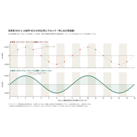
1. What is NCO NCO (Numerical Controlled Oscillator) is a mechanism that generates sin/cos waves using digital circuits. The output frequency is determined by the increment amount (phiinc). 2. Challenges of Conventional Type The conventional type can only output one sample per clock. The maximum output frequency is half of the clock frequency (fclk / 2). To create high-frequency signals, the only option is to increase the clock speed. 3. Concept of 16 Parallel In one clock, 16 samples (x00 to x15) are output simultaneously. The samples are arranged in chronological order, and the sampling frequency is 16 times the clock frequency (16 × fclk). 4. How to Create Phase The phase of lane k is "reference phase + k × phiinc." The reference phase is created by adding phiinc to the phase of the last lane (x15) from the previous clock. Therefore, the waveform does not break at the clock boundary. 5. Circuit Configuration Input register → Constant multiplication (×0 to ×15) → Addition → Phase register → DDS IP ×16 in that order. The phase loop generates the reference phase for the next clock.
Added to bookmarks
Bookmarks listBookmark has been removed
Bookmarks listYou can't add any more bookmarks
By registering as a member, you can increase the number of bookmarks you can save and organize them with labels.
Free membership registration
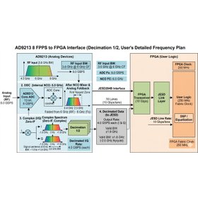
This introduces a system image that downconverts an input center frequency of 6.0 GHz with a bandwidth of 3.6 GHz (frequency range: 4.2 GHz to 7.8 GHz) using the internal NCO (6.0 GHz) of the AD9213 to Zero-IF (Zero-IF / quadrature complex conversion). It is a very advanced and rational frequency plan, illustrating the frequency transition image (spectrum movement) from direct RF sampling to Zero-IF conversion, as well as the consistency of the filter bandwidth for 1/2 decimation in a diagram.
Added to bookmarks
Bookmarks listBookmark has been removed
Bookmarks listYou can't add any more bookmarks
By registering as a member, you can increase the number of bookmarks you can save and organize them with labels.
Free membership registration
1. Achieving improved cutting quality through high-speed pulses and arbitrary waveforms, effective for materials with high thermal conductivity (such as FRP). 2. Over 90% high efficiency, realizing a cutting processing device that operates solely with air cooling and high energy conversion efficiency. 3. Compact, lightweight, and cost reduction, achieved through a simple structure. 【Patent Overview】 Title of Invention: Switching Power Supply Patent Number: Patent No. 7348667 Patent Holder: Edic Systems Co., Ltd. Patent Registration Date: September 12, 2023
Added to bookmarks
Bookmarks listBookmark has been removed
Bookmarks listYou can't add any more bookmarks
By registering as a member, you can increase the number of bookmarks you can save and organize them with labels.
Free membership registration
We have a wide range of experience from large-scale logical implementations and high-density FPGA board development to low-power solutions. - SOC system design (Single board computer development, RFSOC design, Qt touch panel control software) - Signal transmission (MEPG2, TS transmission, TS over IP, SERDES/JESD embedded, etc.) - Baseband signal processing (Over 2 Gsps OTFS/OFDM/SC-FDE implementation, antenna beamforming, MIMO, digital adaptive filters, etc.) - Development boards with RFSOC and FPGA, solution proposals
Added to bookmarks
Bookmarks listBookmark has been removed
Bookmarks listYou can't add any more bookmarks
By registering as a member, you can increase the number of bookmarks you can save and organize them with labels.
Free membership registration
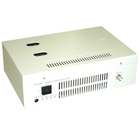
Introducing the YP-1079 series signal generator that is based on rubidium oscillation, operating at 10 MHz.
Added to bookmarks
Bookmarks listBookmark has been removed
Bookmarks listYou can't add any more bookmarks
By registering as a member, you can increase the number of bookmarks you can save and organize them with labels.
Free membership registration
Introducing the ER-1003A signal generator, which is based on rubidium oscillation and operates at 10 MHz.
Added to bookmarks
Bookmarks listBookmark has been removed
Bookmarks listYou can't add any more bookmarks
By registering as a member, you can increase the number of bookmarks you can save and organize them with labels.
Free membership registration
We anticipate the diversifying needs of social infrastructure and evolve the foundation of the future with advanced technologies that integrate analog and digital. As a core supplier contributing to areas that support society, such as Beyond 5G/6G networks, millimeter-wave high-capacity wireless transmission, and power infrastructure, we realize highly reliable and efficient systems. In an era where edge AI and real-time processing are required, we support the realization of a sustainable society with advanced integration technologies. *For more details, please feel free to contact us.
Added to bookmarks
Bookmarks listBookmark has been removed
Bookmarks listYou can't add any more bookmarks
By registering as a member, you can increase the number of bookmarks you can save and organize them with labels.
Free membership registration