- Publication year : 2026
46~53 item / All 53 items
Displayed results
Added to bookmarks
Bookmarks listBookmark has been removed
Bookmarks listYou can't add any more bookmarks
By registering as a member, you can increase the number of bookmarks you can save and organize them with labels.
Free membership registrationContact this company
Inquiry Form46~53 item / All 53 items
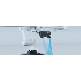
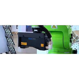
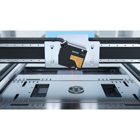
Automation of welding for non-standard shaped, small lot steel structural members. This is a case study of positioning and guiding robot welding using SinceVision's 3D laser profiler "SR7400." ■ Obtaining coordinates of the workpiece and weld area The member is scanned to obtain a three-dimensional contour. Coordinates are extracted using software on a higher-level PC, and planning and condition setting for the welding path are performed. ■ Execute robot welding after confirmation After the operator confirms the created program, robot welding begins. 【Requirements for this case】 Target dimensions: 300×150×100mm Required accuracy: 0.5mm / Required speed: 200mm/s * The above are project requirements and do not represent the guaranteed specifications of the sensor alone. 【Contact Information】 SinceVision Contact: Tao Wei Mobile (Japan): 070-5615-6368 〒530-0001 Osaka City, Kita Ward, Umeda 3-2-123 Innogate Osaka 10F E-Mail: taowei@sincevision.com Web: https://www.sincevision.com
Added to bookmarks
Bookmarks listBookmark has been removed
Bookmarks listYou can't add any more bookmarks
By registering as a member, you can increase the number of bookmarks you can save and organize them with labels.
Free membership registration
Supports correction of welding trajectories according to workpiece deformation and assembly errors. Here are some examples of utilizing SinceVision's integrated 3D laser profiler "SRI7400R." ■ Acquisition of three-dimensional shape of the weld Data on position, shape, and dimensions can be obtained and used for adjusting posture and trajectories on the robot control side. ■ Wide measurement range and high-speed scanning Z-axis measurement range of 339mm and scanning speed of 1,500 to 20,000Hz. Supports data acquisition according to the target object and process. ■ Supports system integration An SDK for Python and C++ is provided to assist with integration into robot systems. *Operation depends on the configuration with the robot and control software. 【Contact Information】 SinceVision Contact: Wei Tao Mobile (Japan): 070-5615-6368 〒530-0001 3-2-123 Umeda, Kita-ku, Osaka Innogate Osaka 10F E-Mail: taowei@sincevision.com Web: https://www.sincevision.com
Added to bookmarks
Bookmarks listBookmark has been removed
Bookmarks listYou can't add any more bookmarks
By registering as a member, you can increase the number of bookmarks you can save and organize them with labels.
Free membership registration
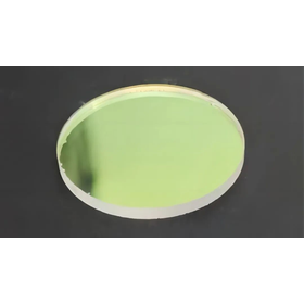
Measuring the thickness of transparent glass non-contact from one side. We introduce a case study of thickness measurement using SinceVision's spectral confocal displacement sensor. ■ Obtaining thickness from the front and back surfaces Using light that passes through the glass, thickness is measured from the positions of the front and back surfaces. Measurements can be taken from one side without touching the object. ■ Evaluating repeatability with 10 dynamic measurements In this case study, the thickness of the transparent glass was measured dynamically 10 times, with a repeatability of 0.001mm (1μm). ■ Supporting quality control of transparent glass By quantifying the thickness, it can be utilized for product thickness management and measurement process considerations. *The values are based on the measurement conditions of this case study and are not guaranteed accuracy values. 【Contact Information】 SinceVision Contact: Wei Tao Mobile (Japan): 070-5615-6368 〒530-0001 3-2-123 Umeda, Kita-ku, Osaka Innogate Osaka 10F E-Mail: taowei@sincevision.com Web: https://www.sincevision.com
Added to bookmarks
Bookmarks listBookmark has been removed
Bookmarks listYou can't add any more bookmarks
By registering as a member, you can increase the number of bookmarks you can save and organize them with labels.
Free membership registration
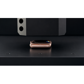
Non-contact measurement of fine step differences, grooves, and sloped curved surfaces. We present a case study of contour measurement of a smartwatch back cover using SinceVision's spectral confocal displacement sensor "SCI03560." ■ 5.8μm fine spot Captures subtle height changes, steps, and grooves on curved surfaces. ■ ±60° angle characteristics Supports measurement of areas with significant slopes and assists in acquiring contour data. ■ 33kHz sampling Scans the surface of the back cover to obtain contours. The non-contact method avoids scratches and wear caused by contact with the measuring element. Confirms height deviations and deformations of curved surfaces, supporting quality control and stabilization of assembly quality. *Results may vary depending on measurement conditions. 【Contact Information】 SinceVision Contact: Wei Tao Mobile (Japan): 070-5615-6368 〒530-0001 3-2-123 Umeda, Kita-ku, Osaka Innogate Osaka 10F E-Mail: taowei@sincevision.com Web: https://www.sincevision.com
Added to bookmarks
Bookmarks listBookmark has been removed
Bookmarks listYou can't add any more bookmarks
By registering as a member, you can increase the number of bookmarks you can save and organize them with labels.
Free membership registration
In a single scan, multiple dimensions of rectangular silicon ingots are obtained. We present a measurement case using SinceVision's integrated 3D laser profiler "SRI series." ■ Scanning the surroundings with four sensors The sensors are arranged at 90° intervals and synchronized with an external signal trigger. The outline of the moving object is captured, and point clouds from four directions are synthesized. ■ Calculating multiple items from cross-sectional shapes The necessary area is extracted from the ROI, measuring the projected length of the arc section, edge distance, diameter, and angle of the straight section. This supports the efficiency of dimensional management. ■ Evaluating repeatability with 32 static measurements In this case, the maximum values were a projected length of the arc section of 0.003mm, edge distance of 0.0051mm, diameter of 0.0048mm, and angle of 0.0088°. ■ Integrated design compatible with equipment incorporation The structure does not require additional controllers, accommodating limited installation space. *The values listed are results from laboratory evaluations. Actual measurement results may vary depending on the measurement environment. For more details, please refer to the related links. 【Contact Information】 Person in charge: Wei Tao E-mail: taowei@sincevision.com
Added to bookmarks
Bookmarks listBookmark has been removed
Bookmarks listYou can't add any more bookmarks
By registering as a member, you can increase the number of bookmarks you can save and organize them with labels.
Free membership registration
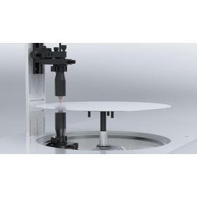
Detecting minute thickness changes in wafers non-contactly. We present a case study of thickness measurement of semiconductor wafers using SinceVision's spectral confocal displacement sensor "SCI04025." ■ Thickness measurement with two sensors positioned above and below Sensors are arranged facing each other on the top and bottom sides of the wafer, and thickness is calculated from the measurement data of both sides. Thickness can be confirmed without touching the measurement target. ■ Evaluating measurements during movement Two points on the wafer were targeted, and automatic measurement was simulated by moving the stage. The changes in thickness and the repeatability of measurements were confirmed under dynamic conditions. ■ Maximum fluctuation of 0.6μm in 10 dynamic measurements In this case study, the difference between the maximum and minimum thickness measurement values was up to 0.6μm. We present the evaluation results aimed at wafer thickness management. *The values are based on the evaluation conditions of this case study and do not represent the resolution or measurement accuracy of the sensor alone. For more details, please refer to the related links or contact us.
Added to bookmarks
Bookmarks listBookmark has been removed
Bookmarks listYou can't add any more bookmarks
By registering as a member, you can increase the number of bookmarks you can save and organize them with labels.
Free membership registration
Quantifying slight height variations of camera support parts non-contactly. We present a case study of measuring the flatness of smartphone camera support parts using SinceVision's integrated laser displacement sensor "SGI030." ■ Calculating flatness from multiple height points Multiple points on the target surface are measured using laser triangulation. The acquired distance data is processed with measurement software to perform plane fitting and calculate flatness error. ■ Pass/fail judgment based on threshold values The calculated flatness error is compared with a set value to determine pass or fail. This helps suppress subjective judgments based on visual inspection and supports quality control in the manufacturing process. ■ Evaluating repeatability with 10 dynamic measurements In this case study, sampling was conducted at 10 kHz. The difference between the maximum and minimum measurement values for each sample was up to 0.0091 mm (9.1 μm), meeting the required value of 10 μm. *Note: The results differ from the specifications of the sensor alone based on the measurement conditions of this case study. Please refer to the related links for more details.
Added to bookmarks
Bookmarks listBookmark has been removed
Bookmarks listYou can't add any more bookmarks
By registering as a member, you can increase the number of bookmarks you can save and organize them with labels.
Free membership registration
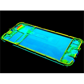
Detection of tiny foreign objects on the surface of FPC from three-dimensional shapes. We present a case study of FPC inspection for smartphone internal frames using SinceVision's 3D laser profiler "SR7140." ■ Inspection of the presence and size of foreign objects The contour data obtained by laser is used to detect surface protrusions. Thresholds for height and area are set to extract foreign objects. ■ Capturing tiny foreign objects In this case study, foreign objects as small as 0.5×0.5×0.3mm can be detected. The scan time during evaluation is 6.5 seconds. ■ Visualizing detection points with point clouds Scanning is performed along the short side of the target object, and the sensor is rotated during the second scan. The position and shape of foreign objects can be confirmed from the three-dimensional point cloud and detection results. *The values mentioned are based on the evaluation conditions of this case study. Results may vary depending on the target object and inspection conditions. For more details, please refer to the related links or contact us.
Added to bookmarks
Bookmarks listBookmark has been removed
Bookmarks listYou can't add any more bookmarks
By registering as a member, you can increase the number of bookmarks you can save and organize them with labels.
Free membership registration