1~37 item / All 37 items
Displayed results
Added to bookmarks
Bookmarks listBookmark has been removed
Bookmarks listYou can't add any more bookmarks
By registering as a member, you can increase the number of bookmarks you can save and organize them with labels.
Free membership registrationContact this company
Inquiry Form1~37 item / All 37 items
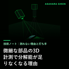
The reason why the resolution is insufficient for 3D measurement of fine parts is that the shape we want to see is smaller than the length that one pixel of the camera can capture or the fineness that the lens can resolve. As the field of view expands, the length that one pixel captures increases, causing fine shapes to be averaged out and disappear. The approaches are to narrow the field of view and magnify, to make the stripes finer and improve height readings, or to switch to a method that is strong in fineness. 【Points】 ■ The shape we want to see needs to be several times larger than one pixel. ■ Expanding the field of view also increases the size of one pixel. ■ When magnifying, the depth of field becomes narrower. *For detailed explanations, please refer to the technical notes and downloadable materials in the related links.
Added to bookmarks
Bookmarks listBookmark has been removed
Bookmarks listYou can't add any more bookmarks
By registering as a member, you can increase the number of bookmarks you can save and organize them with labels.
Free membership registration
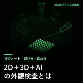
The inspection of appearance using 2D, 3D, and AI involves a division of roles: color and patterns are handled by a 2D camera, shape and depth by a 3D sensor, and the judgment of quality is managed by AI. A 2D system alone cannot determine depth, and a 3D system cannot distinguish color differences. The AI that makes judgments works better with higher quality information. The approach of adding only what is lacking is a reasonable way to proceed. 【Points】 - Color and patterns are handled by 2D, shape and depth by 3D, and judgment is managed by AI. - There is no need to add 3D to inspections that can be adequately performed with 2D. - AI cannot find beyond the quality of the captured information. *For detailed explanations, please refer to the technical notes and downloadable materials linked in the related links.*
Added to bookmarks
Bookmarks listBookmark has been removed
Bookmarks listYou can't add any more bookmarks
By registering as a member, you can increase the number of bookmarks you can save and organize them with labels.
Free membership registration
The number of images required cannot be expressed as a single number. It is determined by the degree of variation in good products, the number of types of defects, and the stability of the shooting method. If the variation is small and the shooting method is stable, you can start with fewer images. When defects are not accumulating, you can begin with only good products and introduce a few defective items for verification purposes. 【Key Points】 ■ The number of images is determined by variation, types of defects, and the shooting method. ■ If the shooting method is unstable, no matter how many images you collect, it will not be sufficient. ■ When defects are not accumulating, you can start with good products. *For detailed explanations, please refer to the technical notes and downloadable materials in the related links.
Added to bookmarks
Bookmarks listBookmark has been removed
Bookmarks listYou can't add any more bookmarks
By registering as a member, you can increase the number of bookmarks you can save and organize them with labels.
Free membership registration
The automation of visual inspection begins by confirming whether the defects you want to find can be captured by the camera, before selecting AI. The process involves determining the defects, taking pictures of the actual items to see how they appear, establishing criteria for good and bad, creating a judgment mechanism, and testing on the production line. By ensuring that you can stop at the stage where you identify defects that cannot be captured, you can avoid waste. 【Key Points】 ■ The first step is not selecting AI, but confirming whether it can capture the images. ■ The criteria should be solidified with physical samples, not just words. ■ Structuring the process so that you can stop at each stage minimizes losses. *For detailed explanations, please refer to the technical notes and downloadable materials in the related links.
Added to bookmarks
Bookmarks listBookmark has been removed
Bookmarks listYou can't add any more bookmarks
By registering as a member, you can increase the number of bookmarks you can save and organize them with labels.
Free membership registration
The reasons for the failure of automating visual inspections often lie not in the judgment mechanism itself, but in three areas: the method of capturing images, the standards used, and the fluctuations in the field. Defects may not be captured in the images, the boundary between good and bad may differ from person to person, and the lighting and transport conditions during the actual operation may differ from those during testing. These three factors can be verified before creating the equipment. 【Key Points】 ■ The causes of failure lie before the judgment mechanism. ■ Defects that are not captured and inconsistent standards cannot be corrected through adjustments in judgment. ■ If something works during testing but fails in practice, it is because the fluctuations in the field have not been considered. *For detailed explanations, please refer to the technical notes and downloadable materials linked in the related links.
Added to bookmarks
Bookmarks listBookmark has been removed
Bookmarks listYou can't add any more bookmarks
By registering as a member, you can increase the number of bookmarks you can save and organize them with labels.
Free membership registration
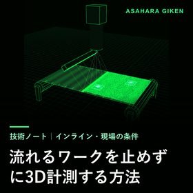
To measure in 3D without stopping the flowing workpiece, the basic method is to shine a linear light and capture cross-sections one by one, stacking them with the flowing motion. The method of taking multiple images and compositing them will collapse if the workpiece moves during shooting. However, the faster the flow, the coarser the spacing of the cross-sections, so speed and detail are a trade-off. [Key Points] - Use the flowing motion to stack cross-sections one by one. - The method of taking multiple images and compositing them collapses if there is movement. - Increasing speed reduces the detail in the direction of flow. *For detailed explanations, please refer to the technical notes in the related links and the downloadable materials.
Added to bookmarks
Bookmarks listBookmark has been removed
Bookmarks listYou can't add any more bookmarks
By registering as a member, you can increase the number of bookmarks you can save and organize them with labels.
Free membership registration
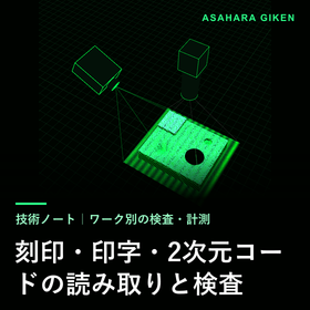
The reasons why engravings, prints, and 2D codes may not be readable are often due to insufficient contrast between the characters and the background or reflections from glossiness. Printed text is read based on the difference in brightness, while engravings are read through the shadows of the unevenness, which means the lighting needs to be adjusted accordingly. Engravings on metals or curved surfaces that do not show contrast may sometimes be readable in 3D by interpreting the unevenness. [Key Points] ■ Many unreadable cases are due to lack of contrast and reflections. ■ Printed text is read by brightness, while engravings are read by shadows of unevenness. ■ For engravings that do not show contrast, there is a method to read the unevenness in 3D. *For detailed explanations, please refer to the technical notes and downloadable materials in the related links.
Added to bookmarks
Bookmarks listBookmark has been removed
Bookmarks listYou can't add any more bookmarks
By registering as a member, you can increase the number of bookmarks you can save and organize them with labels.
Free membership registration
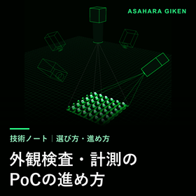
The PoC for inspection and measurement will proceed by first determining the criteria for passing, verifying whether it can be captured, and deciding at each stage whether to continue or stop. Finding out "it couldn't be measured" after creating the device is the most costly failure. The initial stage will be limited to measuring the actual object and reporting up to the range that cannot be measured. 【Points】 ■ The criteria for passing will be determined numerically before starting the verification. ■ In the initial stage, we will only verify whether it can be captured. ■ At the end of each stage, we will decide whether to continue or stop. *For detailed explanations, please refer to the technical notes and downloadable materials in the related links.
Added to bookmarks
Bookmarks listBookmark has been removed
Bookmarks listYou can't add any more bookmarks
By registering as a member, you can increase the number of bookmarks you can save and organize them with labels.
Free membership registration
The results of AI visual inspection are often determined more by how defects are represented in the images than by the type of AI used. AI is a tool for finding differences that are present in the images; it cannot detect differences that are not visible. First, determine the direction of light, the position of the camera, and the arrangement of the workpiece, and then create images where defects stand out from the background before using AI. 【Key Points】 ■ AI can only detect differences that are present in the images. ■ First, look for lighting and camera positions that make defects stand out. ■ Once the shooting method is decided, the part that can be left to AI becomes smaller. *For detailed explanations, please refer to the technical notes and downloadable materials in the related links.
Added to bookmarks
Bookmarks listBookmark has been removed
Bookmarks listYou can't add any more bookmarks
By registering as a member, you can increase the number of bookmarks you can save and organize them with labels.
Free membership registration
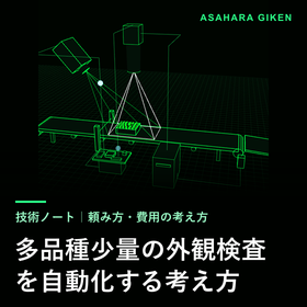
In the case of multi-variety, small-quantity appearance inspections, we design by separating the common parts from the parts that change for each variety, rather than creating separate devices for each variety. The method of lighting and capturing images is standardized, and only the criteria and settings for judgment are switched according to the variety. If the differences between varieties are too large, we narrow the scope of automation. 【Key Points】 ■ We design by separating the common parts from the parts that change for each variety. ■ The effort required for switching is determined by how the settings are maintained and the fixtures used. ■ When there are significant differences between varieties, we limit the varieties that are automated. *For detailed explanations, please refer to the technical notes and downloadable materials in the related links.
Added to bookmarks
Bookmarks listBookmark has been removed
Bookmarks listYou can't add any more bookmarks
By registering as a member, you can increase the number of bookmarks you can save and organize them with labels.
Free membership registration
The cost of appearance inspection equipment is determined by five factors: the difficulty of measuring the workpiece, the time available per unit, the conditions on-site, the degree of finishing, and the range of acceptance. Even if the equipment has the same name, significant variations can occur if these factors differ, making it difficult to use market prices as a reference. Before obtaining a quote, listing the known factors among the five will help narrow down the options. 【Key Points】 ■ Costs are determined by the workpiece, speed, site conditions, finishing, and acceptance range. ■ Even with the same inspection name, costs can vary greatly if the specifics differ. ■ The more items you can decide on before getting a quote, the narrower the options will be. *For detailed explanations, please refer to the technical notes and downloadable materials in the related links.
Added to bookmarks
Bookmarks listBookmark has been removed
Bookmarks listYou can't add any more bookmarks
By registering as a member, you can increase the number of bookmarks you can save and organize them with labels.
Free membership registration
The lighting for visual inspection is chosen based on whether the defects you want to find stand out brightly against the background or appear dark and recessed. The five typical shapes are coaxial, dome, low angle, transmitted, and bar. As a guideline, coaxial is used for scratches or dents on flat glossy surfaces, dome for dirt or prints on curved glossy surfaces, low angle for shallow scratches or edges of unevenness, and transmitted for contours or holes. [Key Points] - The lighting is selected so that defects stand out from the background. - The five typical shapes are differentiated by the angle of light entry and how the surface reflects light. - You cannot target everything with just one type. There are also methods to take shots by changing conditions. *For detailed explanations, please refer to the technical notes and downloadable materials in the related links.
Added to bookmarks
Bookmarks listBookmark has been removed
Bookmarks listYou can't add any more bookmarks
By registering as a member, you can increase the number of bookmarks you can save and organize them with labels.
Free membership registration
3D sensors are selected by working backward from what you want to measure before arranging the numbers in the specification sheet. The four aspects to consider are the field of view, distance, resolution, and speed, along with the conditions under which each value was obtained. The specification sheet often contains values measured with compatible targets, and it is not guaranteed that the same values will be obtained with the materials at hand. Ultimately, you need to verify with the actual object. 【Points】 - First, decide what you want to measure, where you can place it, and how much time you can use. - The numbers in the specification sheet should be read in conjunction with the measured target and conditions. - Compatibility with materials is not listed in the specification sheet, so it must be verified with the actual object. *For detailed explanations, please refer to the technical notes and downloadable materials in the related links.
Added to bookmarks
Bookmarks listBookmark has been removed
Bookmarks listYou can't add any more bookmarks
By registering as a member, you can increase the number of bookmarks you can save and organize them with labels.
Free membership registration
In the contract development of 3D sensors, you can request everything from the selection of the method to the design of optics, mechanics, circuits, and software, as well as evaluation devices and mass production units to be placed on-site. Depending on how you request it, you can receive not only the device but also the source code, the reasons for the design, and the adjustment procedures. There is no need to contract everything at once. You start from the stage of confirming whether it can be measured with a physical object and decide whether to continue at each stage. [Key Points] ■ The range of requests can vary from verification-only requests to mass production units. ■ You can receive not only the device but also the source code and adjustment procedures. ■ Initially, you only request the stage of confirming whether it can be measured with a physical object. *For detailed explanations, please refer to the technical notes and downloadable materials in the related links.
Added to bookmarks
Bookmarks listBookmark has been removed
Bookmarks listYou can't add any more bookmarks
By registering as a member, you can increase the number of bookmarks you can save and organize them with labels.
Free membership registration
In the inspection of machined surfaces, scratches, peeling, and discoloration are often visible in 2D, while the depth of chatter (periodic wave patterns), burr height, and differences in surface roughness require 3D analysis. The way the machined surface shines changes with gloss and grain direction, making it difficult to distinguish between normal tool marks and defects; therefore, the basic approach is to change the direction of the light when taking photographs. 【Key Points】 ■ Scratches, peeling, and discoloration are observed in 2D, while chatter and burr height are assessed in 3D. ■ The direction of the grain on the machined surface affects how it shines. ■ The distinction between normal tool marks and defects should be predetermined numerically. *For detailed explanations, please refer to the technical notes in the related links and the downloadable materials.
Added to bookmarks
Bookmarks listBookmark has been removed
Bookmarks listYou can't add any more bookmarks
By registering as a member, you can increase the number of bookmarks you can save and organize them with labels.
Free membership registration
The inner surfaces of holes and tubes are difficult to illuminate and challenging to direct a camera at. There are two ways to see inside: one is to look from the entrance towards the back, and the other is to insert a thin camera or mirror to view the interior. By unfolding the inner surface like a development diagram of a cylinder, it becomes easier to spot any damage. The deeper you go into a hole, the harder it becomes to see. [Key Points] - The inner surface is a place where light does not reach easily, and it is difficult to point a camera. - The composition changes depending on whether you look from the entrance or insert something inside to view. - The further in you go, the darker and smaller it appears. *For detailed explanations, please refer to the technical notes and downloadable materials in the related links.
Added to bookmarks
Bookmarks listBookmark has been removed
Bookmarks listYou can't add any more bookmarks
By registering as a member, you can increase the number of bookmarks you can save and organize them with labels.
Free membership registration
In the visual inspection of gears and sintered parts, we look for chipping at the tooth tips, dents on the tooth surfaces, burrs, and common issues such as corner chipping and surface voids in the sintered body. Chipping can be seen in 2D as a lack of contour, while the depth of dents and height of burrs are better assessed in 3D. Since rough surfaces and shiny surfaces coexist, it is necessary to consider different approaches for capturing images of each surface. 【Key Points】 - Chipping is a lack of contour and can be seen in 2D. - For assessing the depth of dents and height of burrs, 3D is more suitable. - Rough surfaces and shiny surfaces should be considered separately in terms of imaging. *For detailed explanations, please refer to the technical notes and downloadable materials in the related links.*
Added to bookmarks
Bookmarks listBookmark has been removed
Bookmarks listYou can't add any more bookmarks
By registering as a member, you can increase the number of bookmarks you can save and organize them with labels.
Free membership registration
The gap is the width of the seam, and the flush is the difference in height between adjacent surfaces. The width can be measured in a 2D image, but the step requires height information, so 3D is more suitable. The challenge is that the edges of the seam are rounded, making it difficult to determine where the edge is. We will first define the measurement position. [Points] ■ The gap is the width, and the flush is the difference in height. ■ For steps, 3D is more suitable for measuring height. ■ The rounding of the edge affects how the measurement position is determined. *For detailed explanations, please refer to the technical notes and downloadable materials in the related links.
Added to bookmarks
Bookmarks listBookmark has been removed
Bookmarks listYou can't add any more bookmarks
By registering as a member, you can increase the number of bookmarks you can save and organize them with labels.
Free membership registration
Warping of glass and substrates is measured by assessing the height across the entire surface and determining the deviation from a reference plane. Opaque substrates can be measured all at once using a 3D stripe method. Transparent glass requires careful selection of measurement methods due to light passing through or reflecting off the back surface. Thin plates can change shape depending on how they are supported, so the placement method must also be decided. 【Key Points】 ■ Warping is expressed in terms of the height across the entire surface and the deviation from the reference plane. ■ Transparent glass requires careful selection of measurement methods due to light transmission. ■ The shape can change based on placement and weight, so the support method must also be determined. *For detailed explanations, please refer to the technical notes and downloadable materials linked.
Added to bookmarks
Bookmarks listBookmark has been removed
Bookmarks listYou can't add any more bookmarks
By registering as a member, you can increase the number of bookmarks you can save and organize them with labels.
Free membership registration
In food appearance inspection, what can be captured in images includes shape and size, browning and color variations, chips and cracks, and foreign objects on the surface. Since even good products differ from one another, it is more suitable to learn the range of permissible variations rather than matching to a fixed shape. Foreign objects inside, as well as taste and texture, cannot be determined from appearance and require different methods. 【Points】 ■ Shape, color, chips, and surface foreign objects can be handled with images. ■ Due to significant individual differences in good products, the permissible range is determined by AI or standards. ■ Foreign objects inside, as well as taste and texture, cannot be identified from appearance. *For detailed explanations, please refer to the technical notes and downloadable materials in the related links.
Added to bookmarks
Bookmarks listBookmark has been removed
Bookmarks listYou can't add any more bookmarks
By registering as a member, you can increase the number of bookmarks you can save and organize them with labels.
Free membership registration
To measure flatness and warpage for all items, a 3D measurement that can capture the height of the entire surface at once is preferable. Unlike measuring several points on the surface, this method allows us to determine the maximum and minimum deviations from the reference plane based on the overall shape. The results can vary depending on how the item is placed. For thin items that may sag under their own weight, the placement must be decided in advance. 【Key Points】 - Flatness and warpage are derived from the height of the entire surface. - For thin items, the warpage values can change based on how they are placed. - Reflective or transparent surfaces may have missing points that cannot be measured. *For detailed explanations, please refer to the technical notes and downloadable materials in the related links.
Added to bookmarks
Bookmarks listBookmark has been removed
Bookmarks listYou can't add any more bookmarks
By registering as a member, you can increase the number of bookmarks you can save and organize them with labels.
Free membership registration
Defect inspection of film and coating surfaces determines the lighting method based on whether you want to see streaks, pinholes, foreign objects, or unevenness. Holes are viewed with transmitted light, foreign objects with both reflected and transmitted light, and streaks and unevenness with angled or diffused light. If you want to quantify the height of foreign objects or the unevenness of streaks, consider using 3D imaging. The thickness of the coating itself does not appear in images, so it should be combined with dedicated measurement methods. [Key Points] - The lighting method varies for each type of defect. - Holes and foreign objects are easier to see in 2D, and the thickness of the film itself does not appear in images. - The moving sheet is not stopped; it is captured line by line with a line camera. *For detailed explanations, please refer to the technical notes and downloadable materials in the related links.
Added to bookmarks
Bookmarks listBookmark has been removed
Bookmarks listYou can't add any more bookmarks
By registering as a member, you can increase the number of bookmarks you can save and organize them with labels.
Free membership registration
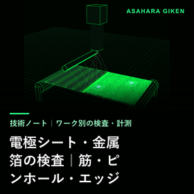
In the inspection of sheets coated with a film on metal foil, like electrode sheets, we look for streaks, pinholes, foreign objects, the position of the coating edge, and wrinkles or undulations in the foil. The presence or absence and position can be seen with a 2D line camera, but since the shiny foil and the dark coating appear in the same image, the visibility of defects changes depending on the lighting. When we want to see the height of protrusions and the shape of wrinkles in numerical form, we consider using 3D. [Key Points] - The shiny foil and dark coating are adjacent, so the appearance changes with lighting. - The position of the coating edge can be measured in 2D as the boundary between light and dark. - If you want to see the height of protrusions and the shape of wrinkles in numerical form, 3D should be added. *For detailed explanations, please refer to the technical notes in the related links and the downloadable materials.
Added to bookmarks
Bookmarks listBookmark has been removed
Bookmarks listYou can't add any more bookmarks
By registering as a member, you can increase the number of bookmarks you can save and organize them with labels.
Free membership registration
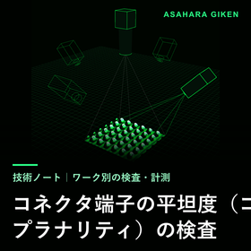
The flatness (coplanarity) of the connector is an inspection that checks how well the tips of all terminals align on the same plane, requiring 3D measurements of the tip heights. In 2D images, you can only see bending, chipping, and dirt. The terminals are small and shiny due to plating, so the basic approach is to change the lighting angle when taking pictures to compensate for any deficiencies. [Key Points] - Flatness is assessed by checking if the tip heights of all terminals align on the same plane. - In 2D, you can see bending and chipping, while the amount of lifting is measured in 3D. - The small, shiny tips are photographed with increased lighting angles. *For detailed explanations, please refer to the technical notes and downloadable materials in the related links.*
Added to bookmarks
Bookmarks listBookmark has been removed
Bookmarks listYou can't add any more bookmarks
By registering as a member, you can increase the number of bookmarks you can save and organize them with labels.
Free membership registration
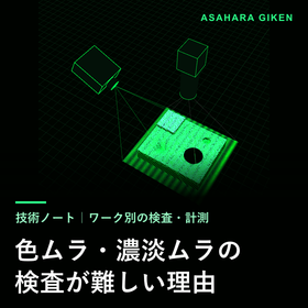
Color variations and gradation inconsistencies do not have clear boundaries like scratches or chips. People assess the gently changing shades based on the angle of view and the lighting. To inspect images, it is necessary to maintain consistent lighting and convert the variations into numerical values. The process of converting the limit samples into numbers determines the success or failure of the inspection. [Key Points] ■ Variations have no boundaries, making it difficult to draw a standard line. ■ The appearance changes depending on the lighting and viewing angle, so conditions are fixed. ■ Measure the limit samples and convert them into numerical standards. *For detailed explanations, please refer to the technical notes and downloadable materials in the related links.
Added to bookmarks
Bookmarks listBookmark has been removed
Bookmarks listYou can't add any more bookmarks
By registering as a member, you can increase the number of bookmarks you can save and organize them with labels.
Free membership registration
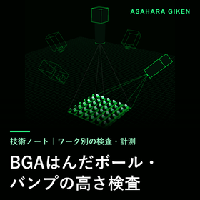
The height of BGA solder balls and bumps cannot be determined from 2D images; 3D measurements are required. What can be seen in 2D are the presence or absence of balls, positional shifts, sizes, and dirt. Since the balls are small and shine like mirrors, the basic method is to illuminate them from multiple directions in sequence and connect the readable spots. 【Points】 ■ The presence and position of the balls are viewed in 2D, while height alignment is assessed in 3D. ■ The apex of the balls is prone to reflection, making it unreadable with light from just one direction. ■ Gaps between the balls may remain as areas that cannot be measured. *For detailed explanations, please refer to the technical notes and downloadable materials in the related links.
Added to bookmarks
Bookmarks listBookmark has been removed
Bookmarks listYou can't add any more bookmarks
By registering as a member, you can increase the number of bookmarks you can save and organize them with labels.
Free membership registration
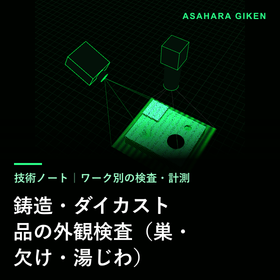
In the visual inspection of cast and die-cast products, defects such as chipping, burrs, and surface voids are often visible in 2D, while the depth of voids, dents, and the height of burrs require 3D inspection. The main difficulty lies in the roughness of the casting surface. The normal surface shines finely, which can obscure defects. Internal voids are not visible through optical means and require different methods. 【Key Points】 - Chipping, burrs, and surface voids are often defects that can be seen in 2D. - The roughness of the casting surface can conceal defects. - Internal voids are not visible through optical inspection. *For detailed explanations, please refer to the technical notes in the related links and the downloadable materials.*
Added to bookmarks
Bookmarks listBookmark has been removed
Bookmarks listYou can't add any more bookmarks
By registering as a member, you can increase the number of bookmarks you can save and organize them with labels.
Free membership registration
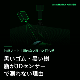
The reason that black rubber and resin cannot be measured by 3D sensors is that their surfaces absorb most of the light that hits them, resulting in insufficient light returning to the camera. The image becomes dark and can be obscured by noise, leading to missing or rough points. The solutions are to increase the returning light, reduce noise, or choose a method to focus the light into a single point. [Key Points] - The cause is that light is absorbed, resulting in insufficient returning light. - Dark images are obscured by sensor noise. - Methods for gathering light and averaging multiple images can be effective. *For detailed explanations, please refer to the technical notes and downloadable materials in the related links.*
Added to bookmarks
Bookmarks listBookmark has been removed
Bookmarks listYou can't add any more bookmarks
By registering as a member, you can increase the number of bookmarks you can save and organize them with labels.
Free membership registration
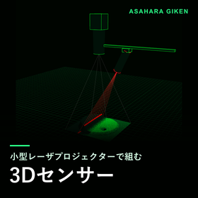
To device manufacturers and development departments looking to integrate small 3D sensors. This is a 3D sensor assembled with a small laser scanning projector and camera. We would like to introduce the content that will be exhibited at CEATEC 2026 in a joint exhibition. This is a joint exhibition with three companies: QD Laser, Inc., which specializes in semiconductor lasers, Ultimems, Inc. (Taiwan), which specializes in MEMS mirrors, and our company, which is responsible for assembling the 3D sensor. 【Features】 ■ Combination of laser scanning projector and camera ■ Demonstration using three methods: phase shift method, moiré method, and optical sectioning method ■ Consistent development of light, imaging, synchronization, and computation by our company ■ 3D reproduction of the booth display on our webpage ■ We welcome inquiries regarding integration into devices and development tailored to specific needs.
Added to bookmarks
Bookmarks listBookmark has been removed
Bookmarks listYou can't add any more bookmarks
By registering as a member, you can increase the number of bookmarks you can save and organize them with labels.
Free membership registration
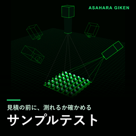
Can our work be measured? For engineers, equipment managers, and purchasing personnel who want to know this first. Before the estimate, we will answer whether it can be measured or not. First, just one photo. A photo taken with a smartphone is fine. Please include three things: material, size, and what you want to see. If there is potential, we will take the actual item and compare measurements using multiple methods. You can request just the initial stage on a small scale. After seeing the results, you can decide whether to continue or stop. 【Features】 ■ The process consists of four stages. What you receive is determined at each stage. ■ Choose from seven methods and compare measurements using the same actual item. ■ We will report the areas that cannot be measured and the reasons for it. ■ Drawings and photos can be shared after a non-disclosure agreement. ■ If off-the-shelf products are sufficient, we will let you know. ■ An engineer will listen to you from the very beginning.
Added to bookmarks
Bookmarks listBookmark has been removed
Bookmarks listYou can't add any more bookmarks
By registering as a member, you can increase the number of bookmarks you can save and organize them with labels.
Free membership registration
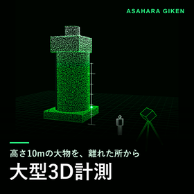
Too large to fit into the measurement room. I want to know the shape and dimensions of places that far exceed a person's height without getting close. For those in manufacturing and equipment management, we develop 3D measurement that captures everything from a distance. We place a sensor mounted on a tripod away from the target. The shape and dimensions from a distance are presented in three dimensions. We measure both fine parts and large items under the same roof. The development of large items is currently being advanced as an actual project. 【Features】 ■ Measures large items up to 10 meters in height from a distance. ■ In our factory, which is approximately 160 square meters and 10 meters high, we verify large items while they are still upright. ■ We report how accurately measurements are obtained and the range of variability. ■ Sensors are custom-built from scratch to match the target and the site. ■ When used outdoors, we confirm the conditions of light and weather with real objects before providing answers.
Added to bookmarks
Bookmarks listBookmark has been removed
Bookmarks listYou can't add any more bookmarks
By registering as a member, you can increase the number of bookmarks you can save and organize them with labels.
Free membership registration
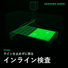
Cannot stop the line, cannot capture the entire scene at once. For those in manufacturing and equipment who want to inspect continuously flowing sheets or workpieces, we capture while they flow and mark the locations of defects. When capturing based on time, the image stretches and shrinks when the speed changes. Our company captures one line at a time according to the distance advanced and stitches them together into a single image. Marks are left at the locations of defects, indicating where they were. 【Features】 ■ Captures one line at a time with a line camera while flowing ■ Captures according to signals of advanced distance (such as encoders) ■ The position of defects is retained, allowing tracking in later processes ■ Determines the capturing method by calculating backwards from the available time (tact) per piece ■ Considers a structure for capturing while keeping the current transport as is ■ If it cannot be done in time, we will communicate that.
Added to bookmarks
Bookmarks listBookmark has been removed
Bookmarks listYou can't add any more bookmarks
By registering as a member, you can increase the number of bookmarks you can save and organize them with labels.
Free membership registration
We want to have a robot grasp overlapping parts inside a box. We will develop a 3D vision system for robots that determines the position and orientation in three dimensions. When shiny metal parts overlap, one eye cannot see the back side of the parts. When external light or mist overlaps, the shape becomes distorted. What a robot needs are a brain, muscles, and eyes. Our company creates that eye, assembling it from scratch to fit the conditions on-site. 【Features】 - There are two ways to position the eye: either place it above to look down or mount it on the robot's hand. - By using two eyes, we can fill in the missing side. - We take measures against external light and mist by selecting the color of light and enclosing it. - We report the conditions that cause distortion and those that did not return to normal. - We can provide the entire assembly process, allowing customers to increase their units from the next one onward.
Added to bookmarks
Bookmarks listBookmark has been removed
Bookmarks listYou can't add any more bookmarks
By registering as a member, you can increase the number of bookmarks you can save and organize them with labels.
Free membership registration
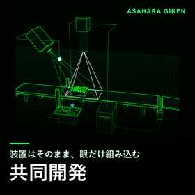
For equipment manufacturers who want to incorporate inspection and measurement functions into their own devices, and for component manufacturers who have been asked to propose a "system" involving cameras, lenses, light sources, and projectors. We will integrate only the parts related to viewing and measuring. You can keep your current designs for transport, enclosures, safety, and control. From the perspective of the device, it will simply send a "measure" command and receive the results. 【Features】 ■ Responsibilities are clearly divided (transport, enclosure, safety, control, and customer interface are handled by the manufacturer) ■ The connection points are only the signal input and output ■ We will consider configurations that allow capturing images without stopping transport ■ We will measure with specified equipment and communicate any deficiencies along with alternative suggestions ■ We can accept projects without mentioning our company name ■ You can consult with us while keeping the end user's name confidential.
Added to bookmarks
Bookmarks listBookmark has been removed
Bookmarks listYou can't add any more bookmarks
By registering as a member, you can increase the number of bookmarks you can save and organize them with labels.
Free membership registration
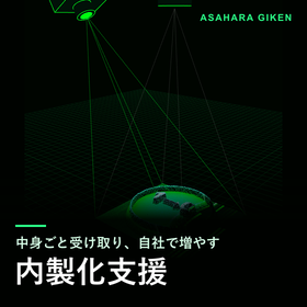
To the production technology and development departments that want to create, repair, and expand inspection devices and 3D sensors themselves rather than buying them. Along with the first unit, we will provide you with instructions on how to make it. If you only receive the device, you won't be able to see inside. You will have to wait for the company that made it to repair or expand it. We will provide you with drawings, source code, and adjustment procedures together. 【Features】 ■ We will choose the method together and share the reasons for our choices. ■ We will provide measurement and inspection software in a form that allows customers to modify it. ■ The design documents and startup procedures will include explanations of "why we did it that way." ■ We will document the "synchronization" of the moment the light is applied and the moment it is captured. ■ We will support the responsible person until they can repair it themselves and expand to the next stage. ■ If the number of units is small and conditions remain unchanged, we recommend the finished product.
Added to bookmarks
Bookmarks listBookmark has been removed
Bookmarks listYou can't add any more bookmarks
By registering as a member, you can increase the number of bookmarks you can save and organize them with labels.
Free membership registration
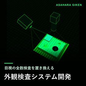
We want to replace visual inspection with machines for quality assurance and manufacturing. Color and scratches are assessed in 2D, shape in 3D, and judgment is made by AI. We will develop a testing system that combines only what is necessary, tailored to the actual product. The reason why automation of visual inspection often fails is usually due to the way images are captured. Defects that are not visible cannot be detected by AI. Before using AI, we will explore the light and angles that reveal defects. 【Features】 - We will first determine the method of capturing images that reveals defects and inform you about defects that will not be visible. - We will assess dents and depressions not by "whether they exist" but by "how deep they are." - If switching lighting is sufficient, we will not use 3D. - We will also consider configurations that add height while retaining the current 2D inspection. - The criteria for over-detection and missed detections will be jointly established using actual good and defective products.
Added to bookmarks
Bookmarks listBookmark has been removed
Bookmarks listYou can't add any more bookmarks
By registering as a member, you can increase the number of bookmarks you can save and organize them with labels.
Free membership registration
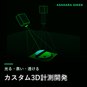
We have tried off-the-shelf 3D sensors, but they miss points, have white out areas, and are rough. For those in production technology and quality assurance with such challenges, we will identify the reasons for measurement failures with real objects and develop suitable measurement methods. The reasons for measurement failures are often related to how light reflects. Shiny objects appear white out, transparent objects show the back surface, and black objects do not reflect light. Our company does not decide on a method in advance; instead, we measure and compare the same real object using multiple methods. 【Features】 - We select candidates from seven methods and compare measurements with real objects to choose the best one. - We address shadows and white out areas by increasing the number and direction of light and eyes. - We will document the areas and reasons for measurement failures in the initial report. - If it is possible to utilize your current sensors, we will inform you. - We also accept inquiries about measuring without spraying.
Added to bookmarks
Bookmarks listBookmark has been removed
Bookmarks listYou can't add any more bookmarks
By registering as a member, you can increase the number of bookmarks you can save and organize them with labels.
Free membership registration